Advertisement
Quick Links
PART NUMBERS:
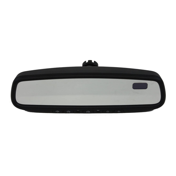
0000-8C-Z02 Electrochromic Mirror w/ Compass/ HomeLink®
0000-8C-L07 Compass / HomeLink® Installation Kit
REQUIRED COMPONENTS:
ITEM
QTY
1
1
INSTALLATION KIT COMPONENTS:
2
1
3
2
4
4
5
1
6
1
7
1
5
TOOLS REQUIRED:
Wire Cutters
Clean Rag
Fiberstick
Electrical Tape
Pliers
#T20 Torx
Page 1 of 8
GENUINE ACCESSORIES
INSTALLATION INSTRUCTIONS
DESCRIPTION
Mirror Assembly with Compass
Harness Assembly – Power and Ground
Wire Tap
Tie Wrap (Short)
Wire Cover
Installation Instructions
User Guide
HOMELINK
Ratchet
10mm Socket
4mm Flat Screwdriver
4
®
®
AND THE HOMELINK HOUSE
ARE REGISTERED TRADEMARKS OF JOHNSON CONTROLS, INC.
Revision A
APPLICABLE MODELS:
2006 >Mazda3
(non-rain sensor models)
SERVICE PART NUMBER
0000-8C-Z02
0000-8C-H12
000-8C-H09
--
000-8C-H11
--
--
550-0336
Advertisement

Subscribe to Our Youtube Channel
Related Manuals for Mazda 0000-8C-Z02


Summary of Contents for Mazda 0000-8C-Z02
-
Page 1: Installation Instructions
GENUINE ACCESSORIES INSTALLATION INSTRUCTIONS PART NUMBERS: APPLICABLE MODELS: 0000-8C-Z02 Electrochromic Mirror w/ Compass/ HomeLink® 2006 >Mazda3 0000-8C-L07 Compass / HomeLink® Installation Kit (non-rain sensor models) REQUIRED COMPONENTS: ITEM DESCRIPTION SERVICE PART NUMBER Mirror Assembly with Compass 0000-8C-Z02 INSTALLATION KIT COMPONENTS: Harness Assembly –... - Page 2 INSTALLATION PRECAUTIONS / NOTES: INSTALLATION PRECAUTIONS / NOTES: • • Do not use excessive force when removing OE mirror from windshield. Do not use excessive force when removing OE mirror from windshield. • • Do not place wire harness against objects with sharp edges that may cause electrical Do not place wire harness against objects with sharp edges that may cause electrical shorting.
- Page 3 3. Remove driver-side kick plate. a) Use 4mm screwdriver to release center of plastic push-pin. b) Grasp kick plate at rear and pull out Push-pin towards passenger-side of vehicle. (Fig. 1-4) Fig. 1-4 4. Loosen driver-side door seal past top of A-pillar.
- Page 4 EC Mirror Installation 1. Plug 10-pin connector into back of EC mirror. (Fig. 2-1) NOTE Slide harness sleeve as close to mirror connector as possible. Fig. 2-1 2. Attach EC mirror. a) Hold the mirror head and slide the mount downwards as far as possible over the windshield button, until fully seated.
- Page 5 CAUTION 3. Route EC harness down driver-side A-pillar. Wraps a) Route power harness along factory harness in driver-side A-pillar. (Fig. 3-3) b) Secure power harness to factory harness with three (3) tie wraps. (Fig. 3-3) CAU TION Fig. 3-3 Verify mirror harness path is clear of air bag (if equipped). CAUTION Do not tie wrap harness to sunroof drain tube (if equipped).
- Page 6 2. Connect EC power harness to ground. a) Locate 10mm ground bolt, upper left of wire Ground bundle in driver-side kick-plate area. (Fig. 4-3) Wire b) Using 10mm socket, remove bolt. c) Place ground ring from EC power harness, over bolt and re-install bolt.
- Page 7 In a few seconds, the mirror will begin to darken. c) Remove the cover from the forward looking photo cell and the mirror will begin to clear. d) Verify that either a direction, such as NE, or “C” is displayed in the display window. If not, ensure the feature is turned ON by pressing the button.
- Page 8 Compass Calibration (Dealer Install ONLY) 1. Calibrate compass. a) Drive to an open, level area, away from large metallic objects or structures. b) Hold the right button for approximately 9 seconds until “C” text appears in the display. Release the right button to enter the calibration mode. c) Drive slowly in up to 3 circles until the “C”...
Need help?
Do you have a question about the 0000-8C-Z02 and is the answer not in the manual?
Questions and answers