Table of Contents
Advertisement
Quick Links
Thank you for purchasing a Genuine Mazda Accessory.
Before removal and installation, Please thoroughly read these instructions.
For your safety, please read the contents of this booklet to properly install and use the Digital
Rearview Mirror. Keep these instructions with your vehicle records for future reference.
· There are several
installing or removing the Digital Rearview Mirror. Always read and follow the instructions in order to prevent
injuries, accidents, and possible damage to the vehicle.
!
WARNING: Indicates a situation in which serious injury or death could result if the warning
!
CAUTION:
· For areas indicating the tightening torque in this instruction manual, tighten to the specified torque by
using a torque wrench. For areas in which the tightening torque is indicated inside parentheses ( ), the
tightening torque is indicated as a reference value, however tightening using a torque wrench is not
necessary.
· Do not modify the Digital Rearview Mirror or kit components.
· Do not install the Digital Rearview Mirror in any way other than described in the following instructions.
· If in doubt, please contact your Mazda dealer to install the accessory in order to prevent errors in installation.
· If you have any questions about the use of the accessory, ask your Mazda dealer for proper advice before
using it.
· Mazda and its suppliers are not responsible for injuries, accidents, and damage to persons and property
that arise from the failure of the dealer or installer to follow these instructions.
· To ensure safety and reliability of the work, installation, removal and disposal work must be carried out by an
Authorized Mazda Dealership.
· Be careful not to lose removed parts, and be sure that they are kept free of dirt, scratches, or damage.
MAZDA NORTH AMERICAN OPERATIONS
GENUINE DIGITAL REARVIEW MIRROR
GENUINE DIGITAL REARVIEW MIRROR
INSTALLATION INSTRUCTIONS
INSTALLATION INSTRUCTIONS
W A R N I N G and
!
!
is ignored.
Indicates a situation in which bodily injury or damage to the vehicle could
result if the caution is ignored.
PART NAME:
PART NUMBER:
VEHICLE:
!
WARNING
C A U T I O N sections in this booklet concerning safety when
Digital Rearview Mirror
KMV6V7210/KMS6V7210
MAZDA CX-90
550-0775
Rev. AAA
*550-0775-000*
Advertisement
Table of Contents

Related Manuals for Mazda KMV6V7210


Summary of Contents for Mazda KMV6V7210
- Page 1 · Do not install the Digital Rearview Mirror in any way other than described in the following instructions. · If in doubt, please contact your Mazda dealer to install the accessory in order to prevent errors in installation. · If you have any questions about the use of the accessory, ask your Mazda dealer for proper advice before using it.
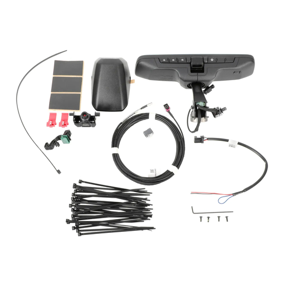
- Page 2 1. PARTS • Verify that the kit includes all the following parts and that the parts are not dirty, scratched, or damaged. Digital Rearview Mirror Kit (KMV6V7210/KMS6V7210) Part Part name Part Part name Mirror Assembly Electro Tap Mini Parts Kit...
-
Page 3: Installation View
2. INSTALLATION VIEW Page: 3 of 35... -
Page 4: Before Installation
3. BEFORE INSTALLATION REQUIRED TOOLS ☆ ☆ ☆ ☆ Mini flathead screwdriver Side cutter Tape-wrapped flathead screwdriver Ratchet ☆ ☆ ☆ ☆ 10mm socket Mini Scissors Trim clip remover/tack puller Nylon trim remover ☆ ☆ ☆ ☆ Small metal scale ruler Electrical tape 90 degree needle nose pliers Small utility knife... -
Page 5: Connector Diagram
Branch connection procedure using electro tap 1. Insert the vehicle wiring harness into the electro tap. 2. Fold the electro tap as shown in the figure and lock Caution Firmly engage the lock part until a click sound is heard. 3. - Page 6 Caution Be careful not to damage or lose any parts removed from the vehicle since they will be reused. Negative Battery Terminal Disconnection a) Open rear liftgate before disconnecting battery. b) Disconnect negative battery terminal according to vehicle workshop manual. SEE WARNING ON PAGE 5 REGARDING HIGH VOLTAGE.
- Page 7 Indicator Sensor Removal a) Disengage side locking tabs with small flathead screwdriver while lightly pushing the indicator assembly forward as shown. b) Disconnect wire cover. Front Door Sill & Weather Seal Removal a) Use a nylon trim removal tool to pop door sill off of vehicle starting at the front and working your way towards the rear.
- Page 8 Rear Door Sill & Weather Seal Removal a) Open driver side rear door and move second row seat all the way forward. b) Use a nylon trim tool to pop door sill off of vehicle starting at the front and working your way towards the rear. c) Lift door sill up and away from the vehicle to remove.
- Page 9 f) Gently loosen and partially lift the upper, left hand, and lower portion of the rear hatch weather seal, but do not remove from vehicle body. Lift just enough to expose gap between vehicle body and interior trims. Caution Removing weather seal from vehicle will expose sealant adhesive which can stain vehicle and is difficult to remove.
- Page 10 i) Remove rear cargo trim by first lifting up using a nylon trim removal tool to disengage clips (1) and then pulling out through trunk opening (2). :TABS A-Pillar Trim Removal NOTE Do not use excessive force. A-pillar could be damaged. a) Pull out the top portion of A-pillar trim towards passenger-side of vehicle until A-pillar push-pin connector is extended approximately 1 1/2”.
- Page 11 d) Move tabs in the directions of arrows (1) and (2) using a mini flathead screwdriver and detach A-pillar clip portion still attached to the vehicle body A-pillar area. e) Remove the grommet in the direction of the arrow (3). NOTE A-pillar connector must be replaced with the supplied tether clip.
- Page 12 Hood Release Lever Removal a) Affix protective tape around the Hood release lever as shown. b) While pulling the hood release lever, insert a flat nylon trim removal tool into the position shown in the figure. c) Insert a tape-wrapped flathead screwdriver into the position shown in the figure and rotate it in the direction of arrow (1) to detach the hood release lever from the driver-side lower panel.
- Page 13 Driver-Side Air Vent Removal a) Affix protective tape around the panel as shown. b) Carefully pry the information panel out from the dashboard to detach the clips from the dashboard, driver-side side panel and driver-side lower panel. Caution Cover the steering column, steering wheel and light switch with a cloth to avoid damage when detaching.
- Page 14 d) Disconnect the cluster switch connectors. e) Remove the driver-side lower panel. f) Insert a tape-wrapped flathead screwdriver in the direction shown in the figure and detach the tabs for Data link connector-2 from the driver-side lower panel bracket. g) Disconnect the Data link connector-2, and then remove the driver-side lower panel from the vehicle.
- Page 15 Connector Connector b) Using a nylon trim removal tool, start at the rear end of the trim and begin disengaging the retention clips in the order shown. c) Lightly pull trim away from vehicle and disconnect wire harnesses. d) Finish removing trim panel from vehicle. Page: 15 of 35...
- Page 16 e) Locate cargo hook on lower left panel and lower bolt cover. f) Use a 10mm socket to remove retention bolt and remove cargo hook from vehicle. g) With the rear seats upright, use masking tape to mask off the area shown just below the cargo hook area. h) Use a nylon trim removal tool to pop off lower trim panel.
- Page 17 WARNING Warning: Removing the lower trim trunk panel on PHEV models will Warning: High Voltage Wires expose high voltage components. and Connectors Coming into contact or disrupting components can result in serious elec- tric shock. Take great caution to not touch any orange wires, connectors, or the electrical modules that they are plugged into.
- Page 18 D-Pillar Trim Removal a) Using a nylon trim removal tool, disengage D-pillar trim clips and set trim down safely. It is not necessary to remove from seatbelt. Caution Disengage electrical connector for vehicles equipped with Bose sound system. Disengaging Headliner a) Using a trim clip remover/tack puller, disengage the two rear clips attaching headliner to roof.
-
Page 19: Mirror Installation
Liftgate Trim Removal a) Remove upper trim panel from rear liftgate by disengaging at the 5 clip locations shown. A nylon trim removal tool can be used to help this process if necessary. 6. MIRROR INSTALLATION Place Camera a) Clean both interior and exterior of rear window with isopropyl alcohol. -
Page 20: Set Screw
c) Screw in set screws provided (one on each side) Note: Do NOT tighten. Camera position will be adjusted after mounting to windshield. Set Screw d) With the rear liftgate open, tape camera mounting template to the inside of rear window. 1) Align center line. - Page 21 f) Align camera bracket with cutout in installation template and place bracket onto the rear glass. Press, hold, and apply even pressure across the entire surface for one minute. Remove template and discard. g) Gently place ruler so that it’s resting on glass and the black plastic material of the bracket and camera.
-
Page 22: Rubber Boot
Routing Coax Cable Through Rear Liftgate Flat End of 14” Zip Tie a) Route flat end of the supplied 14” zip tie through passenger side rubber boot from the headliner area to the liftgate area. Take extra care to not pull down excessively on the headliner. - Page 23 Top Edge Route cable behind vehicle sheet metal. Heater Cable e) Locate connector end of coax cable and line it up with the top edge of the camera bracket as shown. f) Use a zip tie to secure coax cable behind the plastic T-bracket at location (1) while making sure connector end of cable still aligns with the top edge of camera bracket.
- Page 24 Routing Coax Cable a) Gently pull headliner down just enough to see/route cable. Take extra care to not pull down excessively on the headliner. Doing so can result in damage to the headliner. b) Route cable across headliner and up & over the plastic Foam Tape bracket on the driver side D-pillar area.
- Page 25 B Pillar (14) (13) (12) (11) (10) View From Driver Side Rear Door Vehicle Front f) Continue routing the coax cable down the rear driver side passenger door towards the B-pillar and use five zip ties to secure coax cable to the OE harness (9-14). Make sure to remove all slack, but not fully tighten as this time.
-
Page 26: Fuse Relay Box
(17.5) (17) (16) (15) View From Driver Side Rear Door Vehicle Front h) Continue routing coax cable along OE wire harness towards the fuse relay box and attach using zip ties (15-17.5). Remove all slack, but do not fully tighten. (18) Fuse Relay Box Foot Rest... - Page 27 j) Place two pieces of foam pad to cover top back edge of metal bracket (edge pointing towards engine) above the fuse relay box. Coax cable will be routed behind bracket. k) Route coax cable up and behind the bracket and secure to OE wire harness using a zip tie (19).
- Page 28 (24) (23) (24) (22) (23) Air Bag (22) (21) Air Bag (20) m) Route coax cable up the A-pillar area following the OE harness. Secure using five zip tie at locations (20-24), but do not fully tighten. Zip tie (24) is located slightly inside headliner. WARNING: DO NOT ATTACH COAX CABLE TO AIR BAG LOCATED IN THE LOWER A-PILLAR AREA.
- Page 29 Accessory Mirror Power Harness Installation For vehicles with OE Auto Dimming Mirror, it is not nec- essary to install accessory mirror power harness. a) Proceed to page 31, Step a. For vehicles without OE Auto Dimming Mirror, proceed to the following steps. a) Locate OE harness connector that was unplugged from indicator assembly.
- Page 30 c) Install Electro Taps on the now exposed wires of the vehicle indicator assembly harness position A (green) and E (black). Second wire openings should face towards connector. Refer to page 5 for reference. d) Crimp accessory black mirror harness wire in Electro Tap connected to the wire in terminal E (black wire) in the vehicle harness.
- Page 31 Indicator assembly harness g) Return indicator assembly harness to headliner while leaving only the connector showing and route accessory mirror power harness down hub assembly area using the existing OE bracket/clips. Coax Harness Accessory Mirror Power Harness Install Full Display Mirror a) Once seated flush against mounting base, turn 60 degrees to lock mirror in place.
- Page 32 Attach harness clip and connectors a) Attach wire harness clip to the mirror mounting bracket. b) Connect mirror harness connector. c) Connect the new accessory mirror connector to the existing Auto-Dimming Rearview Mirror Connector that was unplugged earlier in the instructions and seat mirror wiring harness clip back into the receiving bracket in the sensor hub area.
- Page 33 e) Use one zip tie to secure coax cable to accessory power harness (25) while removing all slack from the hub area. Tuck any extra coax cable in headliner area if necessary. f) Fully tighten zip ties and trim all ends so they do not in NOTE: Take caution not to terfere with reassembly.
- Page 34 d) To test dimming function, toggle lever forward towards windshield to place in mirror mode. e) While in mirror mode, using a dark cloth or cardboard, completely cover the forward-looking sensor. Mirror will dim after a few seconds (depending on light conditions). Remove the cover from the forward-looking sensor and the mirror will begin to clear.
- Page 35 9. VEHICLE PART REASSEMBLY Vehicle Reassembly a) Switch vehicle mode to off. b) Place user guide, installation instructions, and allen wrench used to adjust camera, in the clear plastic bag that housed the kit contents. c) Place the bag in vehicle glovebox. d) Remove finger prints, smudges, etc.
Need help?
Do you have a question about the KMV6V7210 and is the answer not in the manual?
Questions and answers