Mazda 0000-8C-Z05 Installation Instructions Manual
Electrochromic mirror w/ compass / temp / hl; compass / temp / homelink installation kit for mazda 5 2006; mazda 5 2007; mazda 5 2008; mazda 5 2009; mazda 5 2010; mazda 5 2011; mazda 5 2012; mazda 5 2013; mazda 5 2014; mazda 5 2015; mazda 5 2016; mazda 5
Advertisement
Quick Links
PART NUMBERS:
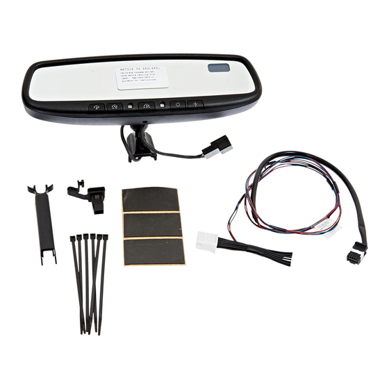
0000-8C-Z05 Electrochromic Mirror w/ Compass/Temp/HL
0000-8C-L27 Compass/Temp/HomeLink
REQUIRED COMPONENTS:
ITEM
QTY
1
1
Mirror Assembly with Compass, Temp and HomeLink
INSTALLATION KIT COMPONENTS:
2
1
Harness Assembly – Power, Battery and Ground
3
2
4
3
5
1
6
1
7
4
8
1
9
1
10
1
11
1
12
1
TOOLS REQUIRED:
Clean Rag
Fish Wire
Fiberstick
Electrical Tape
Pliers
4mm Flat Screwdriver
Page 1 of 13
GENUINE ACCESSORIES
INSTALLATION INSTRUCTIONS
Installation Kit
®
DESCRIPTION
Wire Tap
Foam Tape
Temperature Sensor
Harness Assembly – Temperature Sensor
Tie Wrap (Long)
Tie Wrap (Short)
Wire Cover
Protective Sleeve
Installation Instructions
User Guide
HOMELINK
#T20 Torx
10mm Socket
®
®
AND THE HOMELINK HOUSE
ARE REGISTERED TRADEMARKS OF JOHNSON CONTROLS, INC.
Ratchet
Revision A
APPLICABLE MODELS:
2006 > Mazda5
SERVICE PART NUMBER
0000-8C-Z05
®
000-8C-H12
000-8C-H09
--
000-8C-G18
000-8C-G17
--
--
000-8C-H11
--
--
--
Wire Cutters
Phillip's Screwdriver
550-0339
Advertisement

Related Manuals for Mazda 0000-8C-Z05


Summary of Contents for Mazda 0000-8C-Z05
-
Page 1: Installation Instructions
GENUINE ACCESSORIES INSTALLATION INSTRUCTIONS PART NUMBERS: APPLICABLE MODELS: 0000-8C-Z05 Electrochromic Mirror w/ Compass/Temp/HL 2006 > Mazda5 0000-8C-L27 Compass/Temp/HomeLink Installation Kit ® REQUIRED COMPONENTS: ITEM DESCRIPTION SERVICE PART NUMBER Mirror Assembly with Compass, Temp and HomeLink 0000-8C-Z05 ® INSTALLATION KIT COMPONENTS: Harness Assembly –... - Page 2 INSTALLATION PRECAUTIONS / NOTES: INSTALLATION PRECAUTIONS / NOTES: • • Do not use excessive force when removing OE mirror from windshield. Do not use excessive force when removing OE mirror from windshield. • • Do not push fish wire too far into dash to avoid damage to existing components. Do not push fish wire too far into dash to avoid damage to existing components.
- Page 3 3) Remove passenger-side scuff plate. a) Use fiberstick to disengage clips. (Fig. 1-4) Fig. 1-4 4) Remove passenger-side kick plate. a) Use 4mm screwdriver to release center of plastic pushpin. b) Grasp kick plate at rear and pull out towards rear of vehicle. (Fig.
- Page 4 7) Using fiberstick, remove fuse box cover. (Fig. 1-8) Fig. 1-8 8) Remove passenger-side under-dash cover. a) Depress plastic clips at front edge of cover. b) Lower front edge of cover and remove. (Fig. 1-9) Plastic Clips Fig. 1-9 9) Remove OE mirror. a) Insert fiberstick between bottom of mirror mount and windshield glass.
- Page 5 Temperature Sensor Harness Installation 1) Remove factory temperature probe pre-wire. a) Locate the Red / Black-stripe wire and the Blue / Black-stripe wire, left of vehicle hood latch. b) Verify correct wires by visually tracing them to OEM temperature sensor connector. c) Cut wires off at the point where they protrude Fig.
- Page 6 c) Route temperature probe down through hood latch area along radiator mounting bracket. (Fig. 3-5) Fig. 3-5 CAU TION 4) Attach temperature probe to radiator bracket. Do not pull on probe harness to seat clip. Damage may result. a) Insert tip of probe mounting clip into opening left from factory pre-wire removal.
- Page 7 d) Route temperature harness under radiator overflow tank drain tube and secure to wire bundle with one large tie wrap. e) Route harness under overflow tank mounting Large Tie Wraps bracket towards firewall and secure to A/C pipe with one large tie wrap. (Fig. 3-9) Fig.
- Page 8 Harness d) Pull fish-wire and harness back through rubber grommet and into vehicle glove-box area. Fish Wire (Fig. 3-13) Fig. 3-13 8) Route temperature harness to EC mirror. a) Using fish-wire, route temperature harness from vehicle glove-box area into fuse-box area.
- Page 9 ‘ Complete Installation of Temperature Probe Wires Route temperature harness through black sleeve on power harness. (Fig. 4-1) Fig. 4-1 1 MM 2) Connect temperature harness to 10-pin connector on power harness. a) Using a 4mm flat screwdriver, pry the side tabs of the 10-pin connector block upwards to release the white locking tab (approximately 1 mm.
- Page 10 2. Route harness from mirror to headliner. a) Route mirror harness into groove of wire cover and attach wire cover to mirror base. (Fig. 5-2) b) Slide upper portion of wire cover up to headliner so the “forks” are held by the headliner. (Fig.
- Page 11 f) Route power harness from fuse-box area into passenger-side footwell area. (Fig. 5-6) Connect Harness Power and Ground 1. Attach wire tap connectors to B+ and +12V ignition. Fig. 5-6 a) Locate the OEM wire bundle in passenger-side foot-well area. (Fig. 6-1) b) Locate Blue / Red-stripe wire (B+) in bundle.
- Page 12 Secure Remaining Harness Wires 1. Secure power harness to OEM wire bundle behind white connector with one (1) small tie wrap. (Fig. 7-1) Short Tie Wrap 2. Bundle excess power harness and secure. Fig. 7-1 a) Cover sharp edge of bottom fuse-block mount with one (1) piece of foam tape.
- Page 13 4. Turn the ignition key to the OFF position. 5. Push each HomeLink ® button, one at a time, and verify that LED indicator to the left of the center HomeLink Buttons switch illuminates with a red LED. (Fig. 8-2) 6.
Need help?
Do you have a question about the 0000-8C-Z05 and is the answer not in the manual?
Questions and answers