Table of Contents
Advertisement
Quick Links
GENUINE SATELLITE RADIO KIT
INSTALLATION INSTRUCTIONS
Thank you for purchasing a genuine Mazda accessory.
Before removal and installation, be sure to thoroughly read these instructions.
Please read the contents of this booklet in order to properly install and use the satellite
radio kit. Your safety depends on it.
Keep these instructions with your vehicle records for future reference.
x There are several
safety when installing. Always read and follow them in order to prevent injuries,
accidents, and possible damage to the vehicle.
WARNING: Indicates a situation in which serious injury or death could result if the
warning is ignored.
CAUTION:
Indicates a situation in which bodily injury or damage to the vehicle
could result if the caution is ignored.
x If in any doubt, please ask your Mazda dealer to install the accessory in order to
prevent errors in installation.
x If you have any questions about the use of the accessory, ask your Mazda dealer for
proper advice before using it.
x Mazda and its suppliers are not responsible for injuries, accidents, and damage to
persons and property that arise from the failure of the dealer or installer to follow these
instructions.
x
To ensure safety and reliability of the work, installation, removal and disposal work
done by an Authorized Mazda Dealership is recommended.
x
Be careful not to lose removed parts, and be sure that they are kept free from
scratches, grease or other dirt.
PART NAME:
PART NUMBER:
VEHICLE:
Note
To the dealer
x Please turn over these instructions to the customer after installation.
To the customer
x Keep these instructions after installation. The instructions may be necessary for
installing other optional parts or removal of this accessory.
x
Should the vehicle or this accessory be resold, always leave these instructions
with it for the next owner.
WARNING
WARNING and
CAUTION sections in this booklet concerning
SATELLITE RADIO KIT
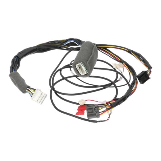
0000 81 L25 (Harness Kit H5)
MAZDA5
(Applicable to 2012 model year vehicle and after)
MAZDA5 1
1ED6P11A23800
Advertisement
Table of Contents

Related Manuals for Mazda 0000 81 L25


Summary of Contents for Mazda 0000 81 L25
- Page 1 Indicates a situation in which bodily injury or damage to the vehicle could result if the caution is ignored. x If in any doubt, please ask your Mazda dealer to install the accessory in order to prevent errors in installation.
-
Page 2: Installation View
INSTALLATION VIEW Antenna ANTENNA CABLE Antenna cable Tie redundant part HARNESS (H5) iPod connection cable) Electro tap CAN (+) and CAN (-) SIRIUS and iPod iPod connection cable Harness (H5) DLP unit Antenna cable To AUX or Bluetooth H/F Electro tap To Audio unit +B and ACC Tie redundant part... -
Page 3: Connection Diagram
CONNECTION DIAGRAM <Installation of SIRIUS and iPod integration module> iPod (On market product) Audio unit iPod connection cable 16 pin connector (White) Audio 24-pin connector 16 pin connector (Black) Harness (H5) iPod integration module NO CONNECT CAN (+) CAN (-) CAN (+) CAN (-) CAN (+) - Page 4 <Installation of SIRIUS only> Audio unit Audio 24-pin connector 16 pin connector (White) 16 pin connector (Black) Harness (H5) CAN (+) CAN (-) Not used (Wrap with sponge and vinyl tape) CAN (+) CAN (-) CAN (-) CAN (+) To dashboard member To AUX or Bluetooth H/F 16 pin connector 16 pin connector...
-
Page 5: Before Installation
Part Part name Qty. Part Part name Qty. Part Part name Qty. Antenna DLP unit Alcohol wipe Harness Kit H5 (0000 81 L25) Part Part name Qty. Part Part name Qty. Part Part name Qty. Double-sided Harness (H5) Pad protector... - Page 6 REQUIRED TOOLS Prepare the following tools or items before installation. Electrical vinyl tape Scissors Scale Touch-up paint or Zinc primer Phillips screwdriver Socket driver (8 mm, 10 mm, 14 mm) Torx wrench Wrench File ISP alcohol WARNING When the negative battery When Do not pull the harness Secure the harness with...
-
Page 7: Battery Cover Removal
PART REMOVAL Battery cover removal Pins B 1. Set the selector lever to D range. (ATX only) WARNING x When removing/installing the parts, park the vehicle on level ground and apply the side brake securely. Be sure to turn the ignition switch off, otherwise the vehicle can move, causing personal injury or vehicle damage. - Page 8 Front side trim (passenger’s side) removal Clip A 1. Partially peel back the seaming welt. Front side trim 2. Remove the fastener. 3. Pull the front side trim in the direction of the arrow and Pin B detach the clip A and pin B. 4.
- Page 9 Front console removal Front console plate 1. Pull the front cup holder upward and detach the tabs A and tabs B to remove the front cup holder from the center console, and disconnect the connectors. 2. Pull the front console plate outward and detach clips C to remove the front console plate from the front console, and disconnect the connectors.
- Page 10 Switch panel removal Switch panel 1. Affix protective tape to the area shown in the figure to protect the switch panel from scratches. 2. Pull the switch panel outward and detach clips A and pins B. 3. Disconnect the hazard switch connector and Bluetooth connector (if equipped).
-
Page 11: Side Panel Removal
Side panel removal Side panel Tab B 1. Pull the side panel in the direction of the arrow (1) shown Hooks A Vehicle front in the figure, then remove the hooks A. CAUTION Hook A When pulling out the side panel, be careful not to damage the tabs B. - Page 12 3. Pull the glove box up shown in the figure, and disengage the hooks C. Vehicle front 4. Remove the glove box. Glove box Hook C Lower panel (passenger’s side) removal Lower panel (passenger’s side) 1. Remove the screws. Vehicle front 2.
- Page 13 B-pillar lower trim (passenger’s side) removal 1. Partially peel back the seaming welt. 2. Pull the B-pillar lower trim in the direction of the arrow (1), (2) shown in the figure, detach tabs A, clips B, pins C. B-pillar lower trim 3.
- Page 14 2. Remove the floor covering installation fasteners. 3. Remove the bolts in the order of (1), (2), (3), (4), (5), then remove the third-row seat. CAUTION Bolt Tightening torque Third-row seat Bolt : 37.0 – 54.0 N m {3.8 – 5.5 kgf m, 28.0 – 39.0 ft lbf} Fasteners Bolt Bolts...
- Page 15 Cargo compartment light removal 1. Insert a tape-wrapped flathead screwdriver in the position shown in the figure, detach the tab by prying it in the direction of the arrow. Vehicle front 2. Disconnect the connector. Trunk side trim 3. Remove the cargo compartment light. Cargo compartment light Trunk side trim Tape-wrapped...
- Page 16 5. Hold c-pillar trim with your hands and pull the trunk side trim in the direction of the arrow (1), (2), (3), (4) and remove hooks A and guides B. Trunk side trim Hook A Guide B Vehicle front 6. Pull the trunk side trim in the direction of arrow, while remove the clips C and pin D.
- Page 17 Rear combination light (passenger’s side) removal 1. Remove the screws. Vehicle front Screws Rear combination light 2. Pull the rear combination light in the direction of the Clip B arrow to detach the hook from clip A. Vehicle front 3. Detach clip B. Hook Clip A Rear combination light...
- Page 18 5. Remove the rear combination light. Cover Clip C 6. Pull the cover in the direction of the arrow shown in the figure and remove the rear combination light while detaching the clips C. Rear combination light Vehicle front Hole cover removal 1.
- Page 19 INSTALLING DLP UNIT 1. Remove the bushes (4 locations), brackets (2 locations), Screw Bush washers (4 locations), and screws (4 locations) from the DLP unit DLP unit. Bracket Note Bush The brackets are not used with the installation of this accessory.
-
Page 20: Installing Antenna
INSTALLING ANTENNA 1. Clean the adhesion area on the roof with isopropyl Roof antenna alcohol (IPA). Vehicle front Adhesion area 100 {3.93} 100 {3.93} mm {in} 2. Install the antenna in the position shown in the figure. Roof antenna CAUTION Vehicle front To ensure proper affixing, be sure to degrease the Antenna... - Page 21 6. Pull the seam upward and route the antenna cable in the seaming welt. (Does not need to be completely removed.) CAUTION It is critical that the antenna follows the route as shown. Failure to follow this route will not provide the Antenna cable slack required to open and close the liftgate.
- Page 22 11. Affix the antenna cable to the body panel using a pad Pad protector (2/3) protector (1/3 and 2/3) and pad protector (thin). Vehicle front CAUTION To ensure proper affixing, be sure to degrease the Antenna cable area where the pad protector is affixed. Body panel Always adhere the pad protector (2/3) on the hole cover with the antenna cable pointed downward.
- Page 23 14. Secure the antenna cable to the vehicle wiring harness Tie wraps (small) with tie wraps (small). Pad protectors (1/4) 15. Affix the antenna cable to the body panel using pad Body panel protectors (1/4). CAUTION To ensure proper affixing, be sure to degrease the area where the pad protector is affixed.
- Page 24 18. Bundle the redundant part of the antenna cable and Tie wrap (small) secure it using a tie wrap (small). 19. Secure the antenna cable and the redundant part to the vehicle wiring harness using tie wraps (small). Tie wrap (small) 20.
- Page 25 24. Secure the antenna cable to the vehicle wiring harness Antenna cable with tie wraps ( large Tie wraps (large) Tie wrap (large) Vehicle front Vehicle wiring harness 25. Connect the antenna cable to the DLP unit. Pad protector (1/2) CAUTION Antenna cable Do not connect the antenna cable with tension...
- Page 26 INSTALLING iPod INTEGRATION MODULE NOTE When installing Sirius only, begin with Step 1 on page 30. 1. Affix the pad protector halves to the iPod integration Pad protector (1/2) module as shown in the figure. CAUTION To ensure proper affixing, be sure to degrease the area where the pad protector is affixed.
-
Page 27: Installing The Harness
INSTALLING THE HARNESS Installation of SIRIUS and iPod integration module 1. Connect the harness (H5) to the DLP unit. DLP unit 2. Route the iPod connector of harness (H5) to the glove box side. To glove box Vehicle front Harness (H5) 3. - Page 28 8. Route a tie wrap (small) to a tie wrap (large) used for Harness (H5) Tie wrap (small) (+B, ACC wires) securing the DLP unit, route the harness (H5) as shown in the figure, and secure it. Harness (H5) CAUTION When reinstalling the audio unit, always secure it using a tie wrap (small).
- Page 29 16. Tighten the harness (H5) GND wire using the vehicle bolt. CAUTION Make sure the ground eyelet contacts the steel bracket. Harness (H5) (GND wire) Vehicle front Bolt (Vehicle part) 17. Bundle the harness (H5) redundant part and secure it using a tie wraps (small).
- Page 30 Installation of SIRIUS only 1. Connect the harness (H5) to the DLP unit. DLP unit 2. Route the iPod connector and electro taps (CAN wires for iPod) for the harness (H5) to the glove box side. To glove box Vehicle front Harness (H5) 3.
- Page 31 6. Branch connect the +B wire to the audio 24-pin connector (terminal B) using the electro tap. Urethane Vehicle front 7. Branch connect the ACC wire to the audio 24-pin connector (terminal R) using the electro tap. Tie wraps (small) Harness (H5) Kit wire Audio 24 pin connector (Vehicle wire)
- Page 32 11. Branch connect the CAN (+) wire (for Sirius) to the [Information display 12 pin connector] information display 12-pin connector (terminal J) using (View from wire side of connector) the electro tap. Terminal L: CAN (-) Kit wire: CAN (-) 12.
- Page 33 18. Tighten the harness (H5) GND wire using the vehicle bolt. CAUTION Make sure the ground eyelet contacts the steel bracket. Harness (H5) (GND wire) Vehicle front Bolt (Vehicle part) 19. Bundle the harness (H5) redundant part and secure it using a tie wraps (small).
- Page 34 2. Press the switch and fully open the window. 3. Pull up the switch and continue holding for about 2 seconds to fully close the window. 4. If the function does not operate even after the ignition switch is turned off, contact an Authorized Mazda Dealer. MAZDA5 34...
- Page 35 INSPECTION x Inspect the installed / reinstalled parts for the following items. x Inspection parts differ depending on the vehicle. Inspection Items ( ) Scratches/ Installation/ Inspection Parts Dirt/ Operation Clearance/Fit Tightening/ Harness check Engagement interference Hole cover Rear combination light (passenger’s side) Trunk side trim (passenger’s side) Cargo compartment light...
Need help?
Do you have a question about the 0000 81 L25 and is the answer not in the manual?
Questions and answers