Advertisement
Quick Links
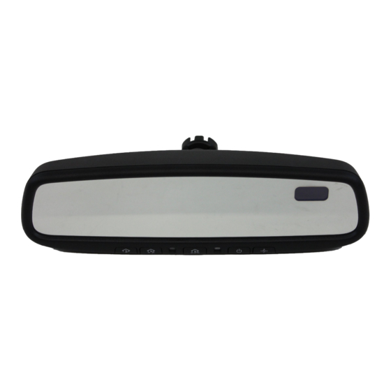
PART NUMBERS:
0000-8C-Z02
Electrochromic Mirror w/ Compass / HomeLink®
0000-8C-G21A Compass / HomeLink® Installation Kit
REQUIRED COMPONENTS:
ITEM
QTY
1
1
Mirror Assembly with Compass and HomeLink
INSTALLATION KIT COMPONENTS:
2
1
3
2
4
6
5
1
6
1
7
1
TOOLS REQUIRED:
Wire Cutters
Clean Rag
Electrical Tape
Fiberstick
#T20 Torx
Pliers
Page 1 of 17
GENUINE ACCESSORIES
INSTALLATION INSTRUCTIONS
DESCRIPTION
Harness Assembly – Power and Ground
Wire Tap
Tie Wrap
Wire Retention Clip
Self-Tapping Hex Screw (8mm)
User Guide
5
®
HOMELINK
AND THE HOMELINK HOUSE
Power Driver with:
- Socket Adapter
- 8mm Socket
APPLICABLE MODELS:
2008 > Mazda Tribute
SERVICE PART NUMBER
®
0000-8C-G26
0000-8C-H09
0000-8C-G27
®
ARE REGISTERED TRADEMARKS OF JOHNSON CONTROLS, INC.
Ratchet
Phillip's Screwdriver
0000-8C-Z02
--
--
--
9/1/2010
Advertisement

Subscribe to Our Youtube Channel
Related Manuals for Mazda 0000-8C-G21A


Summary of Contents for Mazda 0000-8C-G21A
-
Page 1: Installation Instructions
GENUINE ACCESSORIES INSTALLATION INSTRUCTIONS PART NUMBERS: APPLICABLE MODELS: 0000-8C-Z02 Electrochromic Mirror w/ Compass / HomeLink® 2008 > Mazda Tribute 0000-8C-G21A Compass / HomeLink® Installation Kit REQUIRED COMPONENTS: ITEM DESCRIPTION SERVICE PART NUMBER ® 0000-8C-Z02 Mirror Assembly with Compass and HomeLink INSTALLATION KIT COMPONENTS: Harness Assembly –... - Page 2 INSTALLATION PRECAUTIONS / NOTES: • Do not use excessive force when removing OE mirror from windshield. • Do not place wire harness against objects with sharp edges that may cause electrical shorting. • On vehicles equipped with “A” pillar air bag, verify mirror harness path remains clear of air bag.
- Page 3 Grasp A-pillar trim and slide upward. (Fig. 1-4) Fig. 1-4 Fig. 1-4 Retaining Clip Rotate A-pillar trim and allow to hang by tether in order to gain access to A-pillar. Removal of NOTE retaining clip is not needed. (Fig. 1-5) During reassembly, ensure retaining clip is aligned with slot in A- pillar.
- Page 4 5. Remove overhead console. a) Open sunglass holder and remove two (2) Phillip’s screws. (Fig. 1-8) Phillip’s Screw Fig. 1-8 b) Pull toward front of vehicle and downward to remove overhead console. (Fig. 1-9) Fig. 1-9 Removal of OE Rearview Mirror 1.
- Page 5 Route EC Mirror Harness to Vehicle Power 1. Plug 10-pin connector into back of EC mirror. (Fig. 4-1) NOTE Slide harness sleeve as close to mirror connector as possible. Fig. 4-1 Wire 2. Route EC harness from mirror to headliner. Retention Clip a) Route power harness toward passenger side...
- Page 6 CAUTION 4. Route EC harness down A-pillar and secure with (3) CAUTION small tie wraps as shown. (Fig. 4-5) Wraps Verify mirror harness path is clear of air bag (if equipped). CAUTION Do not secure to plastic drain tube if present. Fig.
- Page 7 C214 Locate the Gray wire, Pin #10 (next to Green / Blue-striped wire in pin #6 and the Yellow / Green-striped wire in pin #9). (Fig. 5-3) NOTE Ensure correct wire (pin location 10) is identified. Fig. 5-3 +12V IGN Grey Pin #10 Upper...
- Page 8 Yellow / Green Pin #5 Attach wire tap connector to Yellow / Green- striped wire approximately ½” up from Upper connector. (Fig. 5-7) Connector Using pliers, close 2 sides of wire-tap onto wire. Lower (Fig. 5-7) Connector Fig. 5-7 5. Connect EC power harness to B+ Constant. a) Insert male spade terminal of Solid Black wire into opening of wire tap on the Yellow / Green- striped wire.
- Page 9 C214 Locate the Blue wire, Pin #11 (across from Green / Red-striped wire in pin #4 and the Gray / Violet-striped wire in pin #3). NOTE (Fig. 5-11) +12V IGN Ensure correct wire (pin location 11) is identified. Fig. 5-11 Blue Pin #11 Upper...
- Page 10 Yellow / Green Pin #5 Attach wire tap connector to Yellow / Green- striped wire approximately ½” up from Upper connector. (Fig. 5-15) Connector Using pliers, close 2 sides of wire-tap onto wire. Lower (Fig. 5-15) Connector Fig. 5-15 5. Connect EC power harness to B+ Constant. a) Insert male spade terminal of Solid Black wire into opening of wire tap on the Yellow / Green- CAUTION...
- Page 11 C214 Locate the Blue wire, Pin #1 (across from Green / Red-striped wire in pin #12). (Fig. 5-19) NOTE Ensure correct wire (pin location 1) is identified. +12V IGN Fig. 5-19 Blue Pin #1 Upper Attach wire tap connector to Blue Wire Connector approximately ½”...
- Page 12 Yellow / Green Pin #4 Attach wire tap connector to Yellow / Green- striped wire approximately ½” up from Upper connector. (Fig. 5-23) Connector Using pliers, close 2 sides of wire-tap onto wire. Lower (Fig. 5-23) Connector Fig. 5-23 5. Connect EC power harness to B+ Constant. a) Insert male spade terminal of Solid Black wire into opening of wire tap on the Yellow / Green- CAUTION...
- Page 13 Secure Remaining Harness Wires. Tie Wrap 1. Bundle excess power harness and secure. Bundle any excess power harness wires. Secure bundled harness wires to factory wire bundle in A-pillar with (3) small tie wraps as shown. (Fig. 7-1) CAUTION CAUTION Do not secure to plastic drain tube if present.
- Page 14 Installation of Removed Components 1. Trim excess off all tie wraps. 2. Reinstall in reverse order, all trim pieces removed during installation. User Guide 3. Place User Guide in vehicle glove-box. (Fig. 9-1) 4. Remove fingerprints, smudges, dirt, etc. from mirror. 5.
- Page 15 Inspection • Inspection parts differ depending on the vehicle. • Inspect the installed / reinstalled parts for the following items: Inspection Items ( ) Installation / Inspection Parts Scratches / Dirt / Clearance / Fit Tightening / Operation Check Harness Interference Engagement Negative battery terminal...
-
Page 16: Connector Pinout
5. Check that the TCS/DSC operation indicator is turned off. If the TCS/DSC operation indicator is still illuminated or the DSC indicator is not turned off when the ignition switch is turned back to “ON”, contact your Mazda dealer. Page 16 of 17... - Page 17 3. Lift up the power windows switch to fully close the power windows, and keep it pulled up for approximately 2 seconds. 4. Position the engine switch at “OFF”, and then at “ON” again. If the function doesn’t work after these procedures, please contact your Mazda dealer. Page 17 of 17 9/1/2010...
Need help?
Do you have a question about the 0000-8C-G21A and is the answer not in the manual?
Questions and answers