Advertisement
Quick Links
PART NUMBER:
0000 8C Z01
REQUIRED COMPONENTS:
ITEM
QTY
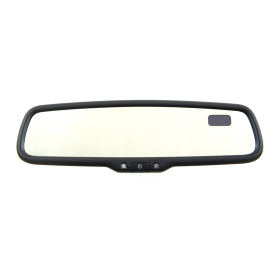
MIRROR ASSEMBLY:
1
1
INSTALLATION KIT:
2
1
3
6
4
1
5
1
6
3
7
1
8
1
**Installation kit may have more components than necessary. Please refer to the chart above and the instructions for required components.
2
1
TOOLS REQUIRED:
10mm Socket
4mm Flat Screwdriver
Clean Rag
Page: 1 of 10
GENUINE ACCESSORIES
INSTALLATION INSTRUCTIONS
DESCRIPTION
Mirror Assembly w/ Compass & HomeLink®
EC Harness - A-Pillar T-Harness
Wire Ties
Wire Cover
A-Pillar Tether Clip (D651-68-162A)
Foam Tape
User Guide
Installation Instructions
5
Ratchet
#T20 Torx Driver
*550-0583-000*
3
6
4
HOMELINK® AND THE HOMELINK HOUSE® ARE REGISTERED TRADEMARKS OF JOHNSON CONTROLS, INC.
Fiberstick
Torque Wrench
550-0583 Rev. AAA
APPLICABLE MODELS:
2013 > MAZDA 6
Usage Chart
1
1
3
1
1
3
1
1
7
8
Needle Nose Pliers
Wire Cutters
11/5/2012
Advertisement

Related Manuals for Mazda 0000 8C Z01


Summary of Contents for Mazda 0000 8C Z01
-
Page 1: Installation Instructions
550-0583 Rev. AAA GENUINE ACCESSORIES *550-0583-000* INSTALLATION INSTRUCTIONS PART NUMBER: APPLICABLE MODELS: 0000 8C Z01 2013 > MAZDA 6 REQUIRED COMPONENTS: ITEM DESCRIPTION Usage Chart MIRROR ASSEMBLY: Mirror Assembly w/ Compass & HomeLink® INSTALLATION KIT: EC Harness - A-Pillar T-Harness... -
Page 2: Connector Diagrams
WIRE CODES CONNECTOR DIAGRAMS Two-color wires are indicated by a two-letter Connector diagrams show connectors on the symbol. The first indicates the base color of the harness side. The terminal indicates the view wire, the second indicates the color of the stripe. from the harness side. - Page 3 INSTALLATION PRECAUTIONS / NOTES: • If using fish wire, use caution to avoid damage to existing components. • Do not place wire harness against objects with sharp edges that may cause electrical shorting. • Verify that power harness path will not interfere with brake, clutch, emergency brake or air bag op- eration. Use wire ties to hold the wiring away from critical locations. Preparation 1. Place kit components on a clean, padded surface, and inspect for damage, defects, or missing components. 2. Record customer’s programmed Radio - AM/FM/SAT stations and trip computer (if applicable). 3.
- Page 4 d) Move the hook in the direction of arrows (1) and (2) using a Flat- head screwdriver and detach it from the A-pillar inner panel. (Fig. 1-4) e) Remove the grommet in the direction of the arrow (3). (Fig. 1-4) f) Install new supplied A-pillar tether clip into A-pillar before proceed- ing.
- Page 5 2. Route EC harness from mirror to headliner. a) Route EC harness into groove of wire cover and attach wire cover to mirror base. (Fig. 3-2) (a) Slide upper portion of wire cover up to headliner so the “forks” are held by the headliner. (Fig. 3-2) Fig.
- Page 6 b) Disconnect the 12-pin connector. (Fig. 4-2) NOTE See Disconnecting Connectors Procedure on Page 2 for detailed in- structions and images of proper connector removal techniques. 12-pin Connector Fig. 4-2 c) Plug the male connector side of the EC harness into the lower OE connector and plug the female connector side of the EC harness into the upper portion of the OE harness.
- Page 7 Testing Compass 1. Reconnect negative battery cable. Display 2. Turn the ignition switch to ON. Photocell Green 3. With the vehicle in a fairly well-lit area, perform the following: a) Verify the shift light on the bottom of the mirror is on and orange. Dark Fig. 6-1 Cloth b) Verify button images are lit with orange back-lighting. c) To make sure the auto-dimming feature is on, verify that the green LED to the left of the center button is on.
- Page 8 Compass Zone Adjustment (Dealer Install ONLY) 1. Adjust compass zone after EC mirror installation. a) The zone setting is factory preset to zone 8. Refer to Compass 9 1 0 1 1 1 2 Calibration Zone Map (Fig. 8-1) to find the correct compass zone setting for your geographical location. Same map is in User Guide as well.
- Page 9 2 seconds. 4. Position the engine switch at “OFF”, and then at “ON” again. When the function doesn’t work after these procedures, please contact your Mazda dealer. CAUTION If the battery is disconnected, the TPMS (Tire Pressure Monitoring System) initial setting is reset and the system may not operate normally.
- Page 10 BASIC INSTALLATION TROUBLE-SHOOTING Verify the following: 1. B+ harness wire (pin 10 at the mirror connector) is receiving +12V with ignition OFF and ON. 2. Switched harness wire (pin 6 at the mirror connector) is receiving +12V with ignition ON and 0V with ignition OFF. 3. Ground wire (pin 3 at the mirror connector) is properly grounded. 4. EC harness is fully inserted into mirror. 5. Ensure jumper connectors are properly installed. 6. EC harness is not pinched, cut or damaged. GAGE COLOR FUNCTION 20 AWG BLACK BATTERY 22 AWG 20 AWG BLACK GAGE COLOR FUNCTION 20 AWG BLACK BLACK 20 AWG 20 AWG BLACK 20 AWG BLACK...
Need help?
Do you have a question about the 0000 8C Z01 and is the answer not in the manual?
Questions and answers