Table of Contents
Advertisement
SIMATIC
ET 200SP
Analog input module
F-AI 4xI 0(4)..20mA 2-/4-wire HF
(6ES7136-6AA00-0CA1)
Manual
Original operating instructions
08/2018
A5E41448857-AB
___________________
Preface
___________________
Documentation guide
___________________
Product overview
___________________
Connecting
___________________
Parameters/address space
Applications of the F-I/O
___________________
module
Interrupts/diagnostic
___________________
messages
___________________
Technical specifications
___________________
Response times
___________________
Representation of analog
values
1
2
3
4
5
6
7
A
B
Advertisement
Table of Contents

Related Manuals for Siemens SIMATIC ET 200SP F-AI 4xI 0(4) 20mA 2-/4-wire HF Series


Summary of Contents for Siemens SIMATIC ET 200SP F-AI 4xI 0(4) 20mA 2-/4-wire HF Series
- Page 1 ___________________ Preface ___________________ Documentation guide ___________________ SIMATIC Product overview ___________________ Connecting ET 200SP Analog input module ___________________ Parameters/address space F-AI 4xI 0(4)..20mA 2-/4-wire HF (6ES7136-6AA00-0CA1) Applications of the F-I/O ___________________ module Manual Interrupts/diagnostic ___________________ messages ___________________ Technical specifications Original operating instructions ___________________ Response times ___________________...
- Page 2 Note the following: WARNING Siemens products may only be used for the applications described in the catalog and in the relevant technical documentation. If products and components from other manufacturers are used, these must be recommended or approved by Siemens. Proper transport, storage, installation, assembly, commissioning, operation and maintenance are required to ensure that the products operate safely and without any problems.
-
Page 3: Preface
Standards You can find a dated reference to the respective standards in the certificate (https://support.industry.siemens.com/cs/ww/en/view/57141281) or in the EC Declaration of Conformity (https://support.industry.siemens.com/cs/ww/en/view/71764057) for the F- module. Certified versions You can find the certified product and firmware versions in annex 1 of the report on the TÜV... - Page 4 The operators of systems with safety-related characteristics must adhere to specific operational safety requirements. The supplier is also obliged to comply with special product monitoring measures. Siemens informs system operators in the form of personal notifications about product developments and properties which may be or become important issues in terms of operational safety.
- Page 5 Siemens' products and solutions undergo continuous development to make them more secure. Siemens strongly recommends that product updates are applied as soon as they are available and that the latest product versions are used. Use of product versions that are no longer supported, and failure to apply the latest updates may increase customers' exposure to cyber threats.
-
Page 6: Table Of Contents
Table of contents Preface ..............................3 Documentation guide ..........................8 Product overview ..........................13 Properties ..........................13 Connecting ............................16 Wiring and block diagram ...................... 16 Parameters/address space ........................20 Measurement types and measuring ranges ................20 Parameters ..........................20 Explanation of parameters ..................... -
Page 7: Analog Input Module F-Ai 4Xi 0(4)..20Ma 2-/4-Wire Hf (6Es7136-6Aa00-0Ca1 Manual, 08/2018, A5E41448857-Ab
Table of contents Technical specifications ........................64 Technical specifications ......................64 Response times ............................ 69 Representation of analog values ......................71 Representation of analog values .................... 72 Analog input module F-AI 4xI 0(4)..20mA 2-/4-wire HF (6ES7136-6AA00-0CA1) Manual, 08/2018, A5E41448857-AB... -
Page 8: Documentation Guide
Documentation guide The documentation for the SIMATIC ET 200SP distributed I/O system is arranged into three areas. This arrangement enables you to access the specific content you require. Basic information The system manual describes in detail the configuration, installation, wiring and commissioning of the SIMATIC ET 200SP. - Page 9 You need to register once to use the full functionality of "mySupport". You can find "mySupport" in the Internet (https://support.industry.siemens.com/My/ww/en). "mySupport" - Documentation In the Documentation area of "mySupport", you have the possibility to combine complete manuals or parts of them to make your own manual.
- Page 10 ● Manuals, characteristics, operating manuals, certificates ● Product master data You can find "mySupport" - CAx Data in the Internet (http://support.industry.siemens.com/my/ww/en/CAxOnline). Application examples The application examples support you with various tools and examples for solving your automation tasks. Solutions are shown in interplay with multiple components in the system - separated from the focus in individual products.
- Page 11 You can find the SIMATIC Automation Tool on the Internet (https://support.industry.siemens.com/cs/ww/en/view/98161300). PRONETA With SIEMENS PRONETA (PROFINET network analysis), you analyze the plant network during commissioning. PRONETA features two core functions: ● The topology overview independently scans PROFINET and all connected components.
- Page 12 Documentation guide SINETPLAN SINETPLAN, the Siemens Network Planner, supports you in planning automation systems and networks based on PROFINET. The tool facilitates professional and predictive dimensioning of your PROFINET installation as early as in the planning stage. In addition, SINETPLAN supports you during network optimization and helps you to exploit network resources optimally and to plan reserves.
-
Page 13: Product Overview
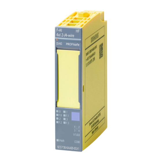
Product overview Properties Article number 6ES7136-6AA00-0CA1 View of the module ① ⑦ Module type and name Function class ② ⑧ LED for diagnostics Color coding module type ③ ⑨ 2D matrix code Function and firmware version ④ ⑩ Wiring diagram Color code for selecting the color identification labels ⑤... - Page 14 Product overview 2.1 Properties ● Supports the "RIOforFA-Safety" profile on F-CPUs S7-1200/1500. ● PROFIsafe address type 2 ● 4 analog inputs with electrical isolation between channels and the backplane bus (up to SIL3/Cat.4/PLd) ● Measuring ranges: 0..20 mA and 4..20 mA ●...
- Page 15 ● Shield connector ● Electronic coding element as spare part (article number 6ES7193-6EF00-1AA0) You can find additional information about accessories in the Distributed I/O System ET 200SP (http://support.automation.siemens.com/WW/view/en/58649293) System Manual. Analog input module F-AI 4xI 0(4)..20mA 2-/4-wire HF (6ES7136-6AA00-0CA1) Manual, 08/2018, A5E41448857-AB...
-
Page 16: Connecting
You can find additional information about wiring BaseUnits in the Distributed I/O System ET 200SP (http://support.automation.siemens.com/WW/view/en/58649293) System Manual. Block diagram The following figure shows the block diagram of the F-AI 4xI 0(4)..20mA 2-/4-wire HF analog input module on the BaseUnit BU type A0/A1. - Page 17 Connecting 3.1 Wiring and block diagram ① Backplane bus interface Sensor supply ② Analog-to-digital converter (ADC) Supply voltage ground ③ Sensor supply/reverse polarity protection Ground to channel n ④ Temperature measurement for BU type 24 V DC (infeed only with light-colored A1 only (the function cannot be used for BaseUnit) this module.)
- Page 18 Connecting 3.1 Wiring and block diagram Recommendation: Internal sensor supply You are strongly advised to use the short circuit-proof internal sensor supply of the F- module. This internal sensor supply is monitored and its status is indicated by the Fn LED. The input is also protected in the event of short-circuits in the wiring or at the sensor.
- Page 19 Connecting 3.1 Wiring and block diagram External/internal sensor supply The figures in section "Applications of the F-I/O module (Page 40)" show how you can supply power to the sensors via an external sensor supply (for example, from another module). WARNING If there is a short-circuit from L+ to Mn+, the input resistors could be destroyed, depending on the selected interconnection type.
-
Page 20: Parameters/Address Space
Parameters/address space Measurement types and measuring ranges The following table shows the measurement types and the respective measuring range. Table 4- 1 Measurement types and measuring ranges Measurement Measuring range Resolution type Current 0 to 20 mA (2-wire and 4-wire transducer) 16 bits including sign 4 to 20 mA (2-wire and 4-wire transducer) 16 bits including sign... - Page 21 Parameters/address space 4.2 Parameters Parameters Value range Default Parameter reas- Scope signment in RUN Behavior after channel faults Passivate channel Module Passivate entire mod- • Passivate channel • Reintegration after channel (S7-300/400) Adjusta- Module Adjustable • fault All channels automati- •...
-
Page 22: Explanation Of Parameters
You can find information on F-parameters for the F-monitoring time, the PROFIsafe addressing (F-source address, F-destination address) and the F-I/O DB in the manual SIMATIC Safety - Configuring and Programming (http://support.automation.siemens.com/WW/view/en/54110126). Analog input module F-AI 4xI 0(4)..20mA 2-/4-wire HF (6ES7136-6AA00-0CA1) Manual, 08/2018, A5E41448857-AB... -
Page 23: Parameters Of The Channels
Here you set the interference frequency suppression for the line frequency: ● 50 Hz ● 60 Hz You can find additional information on this in the Analog value processing function manual (https://support.industry.siemens.com/cs/ww/en/view/67989094). 4.3.2.2 Evaluation of the sensors Overview Here you select the type of sensor evaluation: ●... -
Page 24: Standard Value
A discrepancy error is handled by the safety program in the same way as a channel fault. Additional information is available in the SIMATIC Safety – Configuring and Programming (http://support.automation.siemens.com/WW/view/en/54110126) manual. Analog input module F-AI 4xI 0(4)..20mA 2-/4-wire HF (6ES7136-6AA00-0CA1) -
Page 25: Tolerance Window %, Absolute
Parameters/address space 4.3 Explanation of parameters 4.3.2.5 Tolerance window %, absolute Function If you have selected "1oo2 evaluation (max. SIL3/Cat.4/PLe)", you can enter the size of a tolerance window for the discrepancy here for the channel pair. You specify the tolerance window as a percentage of the full-scale value. -
Page 26: Tolerance Window %, Relative
Parameters/address space 4.3 Explanation of parameters 4.3.2.6 Tolerance window %, relative Function If you have selected "1oo2 evaluation (max. SIL3/Cat.4/PLe)", you can enter the size of a tolerance window for the discrepancy here for each channel pair. You specify the tolerance window as a percentage of the assigned standard value. -
Page 27: Parameter Assignment Of Discrepancy Analysis For 1Oo2 Evaluation
Parameters/address space 4.3 Explanation of parameters 4.3.2.7 Parameter assignment of discrepancy analysis for 1oo2 evaluation Operating principle of discrepancy analysis A discrepancy analysis is performed with a configured 1oo2 evaluation. Smoothed process values are used for the discrepancy analysis. An assignable tolerance window is formed around the process value that represents the instantaneous standard value (value that is signaled to the F-CPU). - Page 28 A discrepancy error is handled by the safety program in the same way as a channel fault. Additional information is available in the STEP 7 Safety – Configuring and Programming (http://support.automation.siemens.com/WW/view/en/54110126) manual Analog input module F-AI 4xI 0(4)..20mA 2-/4-wire HF (6ES7136-6AA00-0CA1)
- Page 29 Parameters/address space 4.3 Explanation of parameters Configuring the discrepancy analysis parameters The following four parameters for the discrepancy analysis are assigned for each channel pair: ● Discrepancy time ● Standard value ● Tolerance window %, absolute ● Tolerance window %, relative "Discrepancy time"...
- Page 30 Parameters/address space 4.3 Explanation of parameters "Tolerance window %, absolute" parameter You can calculate the absolute tolerance window using the following formula: Calculate the maximum deviation of the current using the following formula: With ● I = 20 mA (full-scale value) ●...
- Page 31 Parameters/address space 4.3 Explanation of parameters "Tolerance window %, relative" parameter The tolerance window is calculated as a percentage of the smoothed process value that represents the MIN or MAX value (depending on the parameter assignment of the standard value) in this instant. You can calculate the relative tolerance window using the following formula: Calculate the maximum deviation of the current using the following formula: With...
- Page 32 Parameters/address space 4.3 Explanation of parameters Combination of the "Tolerance window %, absolute" and "Tolerance window %, relative" parameters You can combine the "Tolerance window %, absolute" and "Tolerance window %, relative" parameters as needed. The combined tolerance window (shown in gray in the figure below) is the maximum of T and T T = MAX { T...
- Page 33 Parameters/address space 4.3 Explanation of parameters Example The following diagrams show you the behavior of the discrepancy evaluation when standard value = MAX. The upper of the two diagrams shows you the characteristic curve of the two process values. The dashed line represents the absolute tolerance range configured in this example. The lower of the two diagrams shows you the standard value signaled to the F-CPU.
-
Page 34: Activated
For S7-300/400 F-CPUs you set the corresponding property at the F-I/O DB by means of the ACK_NEC tag. For detailed information about the F-I/O DB, refer to the SIMATIC Safety – Configuring and Programming (http://support.automation.siemens.com/WW/view/en/54110126) manual. 4.3.2.10 Measuring range You select the measuring range for the channel with this parameter: ●... -
Page 35: Diagnostics: Wire Break
Parameters/address space 4.3 Explanation of parameters 4.3.2.11 Diagnostics: Wire break Function Here you activate wire break detection for a configured measuring range of 4 to 20 mA. With an assigned measuring range of 4 to 20 mA: ● With assigned wire break diagnostics and currents < 3.6 mA, a wire break is detected and a diagnostic interrupt is triggered in the F-CPU. - Page 36 Parameters/address space 4.3 Explanation of parameters Smoothing principle The measured values are smoothed by a digital filter. Smoothing is achieved by the F- module forming the mean of a number of converted (digitized) analog values determined by the "Smoothing" parameter. You assign smoothing in 7 levels (1, 2, 4, 8, 16, 32, 64 conversion cycles).
- Page 37 Parameters/address space 4.3 Explanation of parameters Example: Effect of smoothing on the maximum response time for a configured "1oo2 evaluation (max. SIL3/Cat.4/PLe)" in case of error If an error (One Fault Delay Time, OFDT) occurred with a configured "1oo2 evaluation (max. SIL3/Cat.4/PLe)", you calculate the maximum response time according to the following formula: Maximum response time (in case of discrepancy error) = 2 ×...
-
Page 38: Address Space
Parameters/address space 4.4 Address space Address space Address assignment for the analog input module F-AI 4xI 0(4)..20mA 2-/4-wire HF The analog input module F-AI 4xI 0(4)..20mA 2-/4-wire HF occupies the following address areas in the F-CPU: Table 4- 3 Address assignment in the F-CPU Occupied bytes in the F-CPU: F-CPU In input range... - Page 39 Parameters/address space 4.4 Address space Additional information For detailed information about F-I/O access, refer to the SIMATIC Safety – Configuring and Programming (http://support.automation.siemens.com/WW/view/en/54110126) manual. Analog input module F-AI 4xI 0(4)..20mA 2-/4-wire HF (6ES7136-6AA00-0CA1) Manual, 08/2018, A5E41448857-AB...
-
Page 40: Applications Of The F-I/O Module
You achieve SIL3/Cat.4/PLe with the following applications. The wiring is performed on the suitable BaseUnit. Additional information is available in the Connecting section in the Distributed I/O System ET 200SP (http://support.automation.siemens.com/WW/view/en/58649293) System Manual. Application 1: Safety mode SIL3/Cat.3/PLd with 2-wire transducer Introduction Below you will find the wiring scheme and the parameter assignment of the F-AI 4xI 0(4)..20mA 2-/4-wire HF for... - Page 41 Applications of the F-I/O module 5.1 Application 1: Safety mode SIL3/Cat.3/PLd with 2-wire transducer Current measurement 0/4 to 20 mA, 2-wire transducer Four process signals can be connected to the F-module in this interconnection variant. Sensor supply U is provided by the F-module for 4 channels. You can also supply the sensors by means of an external sensor supply.
- Page 42 Applications of the F-I/O module 5.1 Application 1: Safety mode SIL3/Cat.3/PLd with 2-wire transducer ① Backplane bus interface Sensor supply ② Analog-to-digital converter (ADC) Supply voltage ground ③ Sensor supply/reverse polarity protection Ground reference to U , channel n ④ Temperature measurement for BU type A1 24 V DC (infeed only with light- only (the function cannot be used for this...
- Page 43 Applications of the F-I/O module 5.1 Application 1: Safety mode SIL3/Cat.3/PLd with 2-wire transducer Assignable parameters for application 1 Table 5- 1 Parameters for application 1 of F-AI 4xI 0(4)..20mA 2-/4-wire HF Parameters Range of values in safety mode Behavior after channel faults Passivate the entire F-module •...
-
Page 44: Application 2: Safety Mode Sil3/Cat.4/Ple With 2-Wire Transducer
Applications of the F-I/O module 5.2 Application 2: Safety mode SIL3/Cat.4/PLe with 2-wire transducer Application 2: Safety mode SIL3/Cat.4/PLe with 2-wire transducer Introduction Below you will find the wiring scheme and the parameter assignment of the F-AI 4xI 0(4)..20mA 2-/4-wire HF for ●... - Page 45 Applications of the F-I/O module 5.2 Application 2: Safety mode SIL3/Cat.4/PLe with 2-wire transducer ① Backplane bus interface Sensor supply ② Analog-to-digital converter (ADC) Supply voltage ground ③ Sensor supply/reverse polarity protection Ground reference to U , channel n ④ Temperature measurement for BU type A1 24 V DC (infeed only with light- only (the function cannot be used for this...
- Page 46 Applications of the F-I/O module 5.2 Application 2: Safety mode SIL3/Cat.4/PLe with 2-wire transducer Assignable parameters for application 2 Table 5- 2 Parameters for application 2 of F-AI 4xI 0(4)..20mA 2-/4-wire HF Parameters Range of values in safety mode Standard value •...
-
Page 47: Application 3: Safety Mode Sil3/Cat.3/Pld With 4-Wire Transducer
Applications of the F-I/O module 5.3 Application 3: Safety mode SIL3/Cat.3/PLd with 4-wire transducer Application 3: Safety mode SIL3/Cat.3/PLd with 4-wire transducer Introduction Below you will find the wiring scheme and the parameter assignment of the F-AI 4xI 0(4)..20mA 2-/4-wire HF for ●... - Page 48 Applications of the F-I/O module 5.3 Application 3: Safety mode SIL3/Cat.3/PLd with 4-wire transducer ① Backplane bus interface Sensor supply ② Analog-to-digital converter (ADC) Supply voltage ground ③ Sensor supply/reverse polarity protection Ground reference to U , channel n ④ Temperature measurement for BU type A1 24 V DC (infeed only with light- only (the function cannot be used for this...
- Page 49 Applications of the F-I/O module 5.3 Application 3: Safety mode SIL3/Cat.3/PLd with 4-wire transducer Assignable parameters for application 3 Table 5- 3 Parameters for application 3 of F-AI 4xI 0(4)..20mA 2-/4-wire HF Parameters Range of values in safety mode Behavior after channel faults Passivate the entire F-module •...
-
Page 50: Application 4: Safety Mode Sil3/Cat.4/Ple With 4-Wire Transducer
Applications of the F-I/O module 5.4 Application 4: Safety mode SIL3/Cat.4/PLe with 4-wire transducer Application 4: Safety mode SIL3/Cat.4/PLe with 4-wire transducer Introduction Below you will find the wiring scheme and the parameter assignment of the F-AI 4xI 0(4)..20mA 2-/4-wire for ●... - Page 51 Applications of the F-I/O module 5.4 Application 4: Safety mode SIL3/Cat.4/PLe with 4-wire transducer ① Backplane bus interface Sensor supply ② Analog-to-digital converter (ADC) Supply voltage ground ③ Sensor supply/reverse polarity protection Ground reference to U , channel n ④ Temperature measurement for BU type A1 24 V DC (infeed only with light- only (the function cannot be used for this...
- Page 52 Applications of the F-I/O module 5.4 Application 4: Safety mode SIL3/Cat.4/PLe with 4-wire transducer Assignable parameters for application 4 Table 5- 4 Parameters for application 4 of F-AI 4xI 0(4)..20mA 2-/4-wire HF Parameters Range of values in safety mode Standard value •...
-
Page 53: Interrupts/Diagnostic Messages
Interrupts/diagnostic messages Status and error display LED display The following figure shows the LED display of the F-AI 4xI 0(4)..20mA 2-/4-wire HF. ① DIAG (green/red) ② Channel status (green) ③ Channel fault (red) ④ PWR (green) Figure 6-1 LED display Meaning of the LED displays The following tables show the meaning of the status and error displays. - Page 54 Interrupts/diagnostic messages 6.1 Status and error display DIAG LED Table 6- 1 Error display of the LED DIAG DIAG Meaning Backplane bus supply of the ET 200SP not okay Module parameters not configured Flashing Module parameters configured and no module diagnostics Module parameters configured and module diagnostics •...
- Page 55 Interrupts/diagnostic messages 6.1 Status and error display Channel status/DIAG/channel fault LED Table 6- 3 Status display of the LEDs channel status / DIAG / channel error Channel DIAG Channel Meaning status fault The PROFIsafe address does not match the configured PROFIs- afe address.
-
Page 56: Interrupts
Interrupts/diagnostic messages 6.2 Interrupts Interrupts Introduction The fail-safe analog input module F-AI 4xI 0(4)..20mA 2-/4-wire HF supports diagnostic interrupts. Diagnostic interrupt The F-module generates a diagnostic interrupt for each diagnostic message described in section Diagnostic messages (Page 58). The list below provides an overview of the diagnostic interrupts of the F-module. The diagnostic interrupts are assigned either to one channel or the entire F-module. - Page 57 Interrupts/diagnostic messages 6.2 Interrupts ● Diagnostics memory overflow ● Channel failure acknowledgment ● F-address memory not accessible ● No valid F-address available ● Diagnostics memory overflow ● Undertemperature ● Supply voltage too high ● Supply voltage too low ● Channel/component not available Scope of diagnostic interrupt: Channel ●...
-
Page 58: Diagnostic Messages
Once the fault is eliminated, the F-module must be reintegrated in the safety program. For additional information on passivation and reintegration of F-I/O, refer to the SIMATIC Safety – Configuring and Programming (http://support.automation.siemens.com/WW/view/en/54110126) manual. Table 6- 5 Diagnostic messages of the F-AI 4xI 0(4)..20mA 2-/4-wire HF... - Page 59 Interrupts/diagnostic messages 6.3 Diagnostic messages Diagnostic message Fault Meaning Remedy code Safety-related switch off For safety purposes, channel was switched off due to an error on another channel. Possible causes: Correct the process wiring. • Short circuit is present. • Channel/component tempo- Possible causes: rarily not available...
- Page 60 Interrupts/diagnostic messages 6.3 Diagnostic messages Diagnostic message Fault Meaning Remedy code Module is defective Possible causes: Electromagnetic interference has Eliminate the interference. The • • exceeded limits. module must then be pulled and plugged, or the power switched OFF and ON. The F-module has detected an inter- If the F-module cannot be put back •...
- Page 61 Interrupts/diagnostic messages 6.3 Diagnostic messages Diagnostic message Fault Meaning Remedy code Channel failure acknowl- A channel fault was detected. Confirma- Confirm the channel fault. edgment tion is required to enable the channel. No valid F-address available The F-source address and F-destination Verify that the coding element is pre- address stored in the electronic coding sent.
- Page 62 Information on diagnostics that pertains to all fail-safe modules (for example, readout of diagnostics functions or passivation of channels) is available in the SIMATIC Safety – Configuring and Programming (http://support.automation.siemens.com/WW/view/en/54110126) manual. Analog input module F-AI 4xI 0(4)..20mA 2-/4-wire HF (6ES7136-6AA00-0CA1) Manual, 08/2018, A5E41448857-AB...
-
Page 63: Value Status
You can find the assignment in section Address space (Page 38). Reference A detailed description of the evaluation and processing of the respective input signals can be found in the SIMATIC Safety – Configuring and Programming (http://support.automation.siemens.com/WW/view/en/54110126) manual. Analog input module F-AI 4xI 0(4)..20mA 2-/4-wire HF (6ES7136-6AA00-0CA1) Manual, 08/2018, A5E41448857-AB... -
Page 64: Technical Specifications
Technical specifications Technical specifications Technical specifications of the F-AI 4xI 0(4)..20mA 2-/4-wire HF Article number 6ES7136-6AA00-0CA1 General information Product type designation F-AI 4xI 0(4) ... 20 mA 2/4-wire HF Firmware version FW update possible • usable BaseUnits BU type A0, A1 Color code for module-specific color identification CC00 plate... - Page 65 Technical specifications 7.1 Technical specifications Article number 6ES7136-6AA00-0CA1 Address area Address space per module 14 byte; S7-300/400F CPU, 13 byte Inputs • 5 byte; S7-300/400F CPU, 4 byte Outputs • Hardware configuration Automatic encoding Electronic coding element type F • Analog inputs Number of analog inputs For current measurement...
- Page 66 Technical specifications 7.1 Technical specifications Article number 6ES7136-6AA00-0CA1 Encoder Connection of signal encoders for current measurement as 2-wire transducer • 650 Ω – Burden of 2-wire transmitter, max. for current measurement as 4-wire transducer • Errors/accuracies Linearity error (relative to input range), (+/-) 0.1 % Temperature error (relative to input range), (+/-) 0.023 %/K...
- Page 67 Technical specifications 7.1 Technical specifications Article number 6ES7136-6AA00-0CA1 Potential separation Potential separation channels between the channels • between the channels and backplane bus • between the channels and the power supply of • the electronics Permissible potential difference between the inputs (UCM) 10 Vpp Isolation Isolation tested with...
- Page 68 When the ambient temperature exceeds 55 °C, you must only apply a maximum total current of 3 A to an adjacent F-DQ 4x24VDC/2A PM HF. Dimension drawing See ET 200SP BaseUnits manual See also ET 200SP BaseUnits (http://support.automation.siemens.com/WW/view/en/58532597/133300) Analog input module F-AI 4xI 0(4)..20mA 2-/4-wire HF (6ES7136-6AA00-0CA1) Manual, 08/2018, A5E41448857-AB...
-
Page 69: Response Times
Response times Introduction You will find the response times of the F-AI 4xI 0(4)..20mA 2-/4-wire HF below. The response times are included in the calculation of the F-system response time. Definition of response time for fail-safe analog inputs The response time results from the number of channels/channel pairs, the response time per channel/channel pair, the basic response time and the configured smoothing. - Page 70 Response times Response time in the case of a fault (one fault delay time, OFDT) You can calculate the response time of F-AI 4xI 0(4)..20mA 2-/4-wire HF (one fault delay time, OFDT) as follows: ● According to the following formula if a discrepancy error is present: Typical response time = Conversion cycle time ×...
-
Page 71: Representation Of Analog Values
Representation of analog values In this section we are presenting the analog values for all measuring ranges that you can use with the F-AI 4xI 0(4)..20mA 2-/4-wire HF analog input module. Measured value resolution The analog values are shown as fixed-point number in two's complement. The resolutions shown here are 16 bits including sign. -
Page 72: Representation Of Analog Values
Representation of analog values B.1 Representation of analog values Representation of analog values The following tables list the decimal and hexadecimal values (codes) of the possible current measuring ranges. Table B- 2 Current measuring range 0 to 20 mA Values Current measuring Range range... - Page 73 Representation of analog values B.1 Representation of analog values Table B- 3 Current measuring range 4 to 20 mA Values Current measur- Range ing range Dec. Hex. Diagnostics wire break: No Diagnostics wire break: Yes 32512 7F00 > 22.814 mA Overflow Overflow 32511...
Need help?
Do you have a question about the SIMATIC ET 200SP F-AI 4xI 0(4) 20mA 2-/4-wire HF Series and is the answer not in the manual?
Questions and answers