
Related Manuals for Durr Dental VSA 300 S


Summary of Contents for Durr Dental VSA 300 S
- Page 1 VSA 300 S Installation and operating instructions 0297 9000-606-31/30 ...
-
Page 3: Table Of Contents
Contents Important information Assembly About this document � � � � � � � � � � � � � � � 3 Requirements � � � � � � � � � � � � � � � � � � � � 14 1�1 Warnings and symbols �... - Page 4 Contents Usage 13 Display/handling� � � � � � � � � � � � � � � � � � 28 13�1 Ready for operation � � � � � � � � � � � 28 13�2 Amalgam collector vessel is 95% full �...
-
Page 5: Important Information
Important information About this document Other symbols These symbols are used in the document and These installation and operating instructions on or in the unit: represent part of the unit� Note, e�g� specific instructions regarding If the instructions and information in efficient and cost-effective use of the unit�... -
Page 6: Safety
Important information Safety 2.4 Systems, connection with other devices Dürr Dental has designed and constructed this Additional devices connected with medical elec- unit so that when used properly and for the in- trical devices must be proven to conform with tended purpose it does not pose any danger to their corresponding IEC or ISO standards�... -
Page 7: Only Use Original Parts
Important information Observe the EMC rules concerning medical NOTICE devices Reduced performance character- The unit is intended for use in professional istics due to insufficient distance healthcare facilities (in accordance with IEC between unit and portable HF com- 60601-1-2)� If the appliance is operated in an- munication devices other environment, potential effects on elec- Keep a distance of at least 30 cm be-... -
Page 8: Product Description
(possible variations due to country-spe- section): cific requirements and/or import regulations): VSA 300 S, 230 V AC, 50 Hz ..7125-01/002 Information about replacement parts is available from the portal for authorised VSA 300 S, 230 V AC, 50 Hz with in- specialist dealers at: stalled rinsing unit . -
Page 9: Technical Data
Product description Technical data Electrical data 7125-01 7125-04 7125-03 Nominal voltage 230, 1~ 230, 1~ Electrical frequency Nominal current 2�9 3�4 Motor protection Motor winding overheat protector 160 °C (±5 °C) Rated power Type of protection IP 21 Protection class Protective low voltage 24 ~ Output... - Page 10 Product description Network connection LAN technology Ethernet Standard IEEE 802�3u Data rate Mbit/s Connector RJ45 Type of connection Auto MDI-X Cable type ≥ CAT5 Ambient conditions during storage and transport Temperature °C -10 to +60 Relative humidity < 95 Ambient conditions during operation Temperature °C +10 to +40...
- Page 11 Product description Electromagnetic compatibility (EMC) Interference immunity measurements cover Immunity to interference, near fields of wireless HF com- munication devices Compliant IEC 61000-4-3:2006+A1:2007+A2:2010 Immunity to interference table, near fields of wireless HF communication devices Radio service Frequency band Test level TETRA 400 380 - 390 GMRS 460 430 - 470...
- Page 12 Product description Electromagnetic compatibility (EMC) Interference immunity measurements supply input Immunity to interference, line-conducted disturbances induced by high-frequency fields – AC voltage grid IEC 61000-4-6:2013 0�15 - 80 MHz Compliant ISM frequency bands 6�765 - 6�795 MHz 13�553 - 13�567 MHz 26�957 - 27�283 MHz 40�66 - 40�70 MHZ 80 % AM at 1 kHz...
-
Page 13: Type Plate
Product description 4.1 Type plate The type plate is is located on the noise reduc- tion hood� Type plate 4.2 Evaluation of conformity This device has been subjected to conformity acceptance testing in accordance with the cur- rent relevant European Union guidelines� This equipment conforms to all relevant require- ments�... -
Page 14: Operation
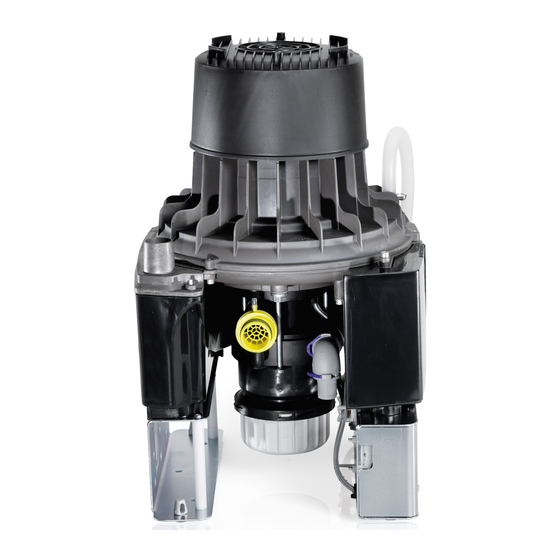
Product description Operation Motor Inlet connection with protective coarse filter Auxiliary air nozzle Waste water connection Amalgam collecting container Control electronics Exhaust air muffler Exhaust air connection Rotational speed sensor The mixture of liquids, solid particles and air drawn in passes through the inlet connection and into the suction unit�... -
Page 15: Tyscor Pulse (Optional)
Product description The fluid and solids accreting in the separation chamber are continuously fed to the amalgam centri- fuge, where the amalgam particles are removed� The fluid extracted via the centrifuge is fed through the waste water valve and the outlet connection into the central waste-water system� Under the centrifuge there is an interchangeable collecting container into which the separated amal- gam particles fall once the motor is switched off�... -
Page 16: Assembly
Assembly Requirements 6.3 Use of nitrous oxide This unit is technically suitable for the aspiration The unit can be installed on the same level as of nitrous oxide (laughing gas)� However, when the surgery room or in a floor below� assembling a system for aspiration of nitrous Further information can be found in our oxide, it is important to ensure that the other... -
Page 17: Installation And Routeing Of Hoses
Assembly 6.6 Installation and routeing of hos- Mains supply cable es and pipes Installation type Line layout (minimum Execute the on-site pipe installation in accord- requirements) ance with the applicable local regulations and Fixed installation – Plastic sheathed cable standards� (e�g�... -
Page 18: System Components
Assembly System components 7.5 Noise reduction If the noise level from the exhaust air vent or the The system components listed below are re- flow noise generated is too high, noise reduction quired or recommended for various procedures can be installed in the exhaust air line� or for installation�... -
Page 19: Installation
Assembly Installation The actual connection can vary depending on the chosen installation option� The connection shown is only an example� 8.1 Installation and routeing of hoses and pipes Establish connections between the pipe system and the unit using the flexible hoses supplied� This will prevent vibrations from being transmitted to the pipe system�... - Page 20 Assembly 11 Hose clip ∅ 28 mm 12 Suction hose ∅ 30 mm (internal) 13 Hose sleeve 14 Waste water hose ∅ 20 mm (internal) 9000-606-31/30 1905V003...
-
Page 21: Rinsing Unit Water Connections
Assembly 8.2 Rinsing unit water connections Check the water pressure for the rinsing unit� The water pressure should be be- tween 2 and 4 bar� Screw the Tecalan hose with sleeve piece, double-tapered ring and locking nut onto the rinsing unit� Apply the T-piece for Tecalan water hose with ∅ 4 mm or ∅ 6 mm in the water supply�... -
Page 22: Electrical Connections
Assembly 8.3 Electrical connections Connect the control line� Connection the display panel� Connect the network cable (optional when using monitoring software)� Establish the electrical connection to the supply network (230 V)� SD Socket T3,15AH H3 H2 (24V AC) (24V AC) Start U1/Z2 T8,0AH 1/N/PE... -
Page 23: 8�4 Connections And Displays Of The Control
Assembly 8.4 Connections and displays of the control H3 H2 X1 Voltage supply for the rinsing unit X2 24V output voltage and switching contact to suction unit in the treatment unit X3 Display panel X4 Sediment sensor light barriers X5 Sediment sensor lifting magnet X6 Collecting container safety switch X7 Motor connection X8 Mains connection... -
Page 24: Display Panel Connection
Assembly 8.5 Display panel connection 8.6 Network connection Purpose of the network connection There must be a direct line connecting The network connection is used to exchange in- the network socket on the unit and the formation or control signals between the unit network socket on the display panel�... -
Page 25: Commissioning
Assembly Commissioning When setting up the PC system in the vicinity of the patients: Only connect components (e�g� computer, NOTICE monitor, printer) that comply with the standard Interference caused by larger par- IEC 60601-1 (EN 60601-1)� ticles such as pieces of tooth or When setting up the PC system outside of the fillings vicinity of the patients:... - Page 26 Assembly Add device Adding the device in the cockpit All devices that are connected to the software can be added to the cockpit� When the unit is Connection icons: first connected to the software, the unit is auto- The unit is present in the network and matically added to the cockpit�...
-
Page 27: Adjustment Options
Assembly 10 Adjustment options Manually starting the device 10.1 Setting the afterrun delay time Manually starting the device for testing� Requirements: The delay time can be set via Tyscor Pulse� – Service technician access level selected� Requirements: Select the device in the device list� Click on the Start button with the left mouse –... -
Page 28: Service Program
Assembly 11 Service program amalgamrecycling DÜRR DENTAL 9000-606-31/30 1905V003... -
Page 29: Description Of The Service Program
Assembly 12 Description of the service 12.3 Sediment level measurement program While the service program is activated, the safety check for the collector vessel Wear protective equipment to avoid any is deactivated� risk of infection (e�g� liquid-tight protec- The sediment level measurement can be used tive gloves, protective goggles, face to check the function of the sediment sensor mask)�... -
Page 30: Display/Handling
Usage 13 Display/handling 13.3 Amalgam collector vessel is 100% full Yellow LED lights up Red display flashes Audible signal melody sounds – At a fill level of 100% the signal melody can no longer be switched off by pressing the reset button�... -
Page 31: 13�5 Motor Fault
Usage 14 Monitoring the unit via the 13.5 Motor fault network Red display and green LED flash alternately As the monitoring system of the device, the software must deliver acoustic sig- Audible signal nals� Audio output on the computer must be activated�... -
Page 32: 14�3 Creating A Report
Usage 15 Disinfection and cleaning If several messages occur, the symbol of the highest message level in each case is displayed� As soon as a message concerning a de- NOTICE vice occurs, the symbol in the task bar Device malfunctions or damage due (or Mac OS menu bar) also changes to to use of incorrect media the relevant message symbol�... -
Page 33: 15�2 Daily After The End Of Treatment
Usage 16 Replace the amalgam col- 15.2 Daily after the end of treatment lector vessel After higher workloads before the midday break and in the evening WARNING The following are required for disinfection/clean- Risk of contamination if the amalgam ing: collector vessel is reused since the –... -
Page 34: 16�1 Disposal Of Amalgam Collecting
Usage 16.1 Disposal of amalgam collecting container The contents of the amalgam collecting container are contaminated with heavy metals and must not be disposed of as household waste or the environment� – Collection and waste disposal by a waste management company specialised in surgery waste�... -
Page 35: Maintenance
Usage 17 Maintenance All maintenance work must be performed by a qualified expert or by one of our Service Techni- cians� Prior to working on the unit or in case of danger, disconnect it from the mains� WARNING Infection due to contaminated unit Clean and disinfect the suction before working on the unit�... -
Page 36: 17�1 Tests
Usage 17.1 Tests Work steps to be performed: Remove the collector vessel� Here, the red LED on the display panel must flash and an WARNING audible signal must sound� Infection due to contaminated unit Insert the test collector vessel� Clean and disinfect the suction before working on the unit�... -
Page 37: Troubleshooting
Troubleshooting 18 Tips for operators and service technicians Any repairs exceeding routine maintenance may only be carried out by qualified personnel or our service� WARNING Infection due to contaminated unit Clean and disinfect the suction before working on the unit� Wear protective equipment when working (e� g�... - Page 38 Troubleshooting Fault Probable cause Solution Suction performance too Coarse filter blocked Clean the coarse filter at the intake connection� Leak in the suction line Check and if necessary establish leak-tightness of suction system and connections� * Mechanical sluggishness of tur- Disassemble the unit and clean bine caused by soiling the turbine�...
-
Page 39: Transporting The Unit
Troubleshooting 19 Transporting the unit WARNING Infection due to contaminated unit Disinfect the unit before transport� Close all media connections� Wear protective equipment to avoid any risk of infection (e�g� liquid-tight protec- tive gloves, protective goggles, face mask)� Before disassembly, clean and disinfect the suction unit and the unit using a suitable disin- fectant approved by Dürr Dental�... - Page 44 Hersteller/Manufacturer: DÜRR DENTAL SE Höpfigheimer Str. 17 74321 Bietigheim-Bissingen Germany Fon: +49 7142 705-0 www.duerrdental.com info@duerrdental.com...
Need help?
Do you have a question about the VSA 300 S and is the answer not in the manual?
Questions and answers