
Related Manuals for Durr Dental Tyscor V 4


Summary of Contents for Durr Dental Tyscor V 4
- Page 1 Tyscor V 4 Installation and operating instructions 0297 7188100023L02 *7188100023L02*...
-
Page 3: Table Of Contents
Contents Contents Overview of the touch screen user interface ....Important information About this document ....Assembly Warnings and symbols . - Page 4 Contents 10.3 Hose manifold start signal ..10.4 Network ....10.5 Fault ..... . 11 Overview on the touch screen .
-
Page 5: Important Information
These installation and operating instructions apply to: Wear protective gloves. Tyscor V 4 Order number: 7188100200; 7188200200 Disconnect all power from the unit. Warnings and symbols Warnings... -
Page 6: Copyright Information
Important information Safety Keep dry Dürr Dental has designed and constructed this unit so that when used properly and for the inten- ded purpose it does not pose any danger to Keep away from sunlight people or property. Despite this, the following residual risks can remain: Stacking limits –... -
Page 7: General Safety Information
Important information The unit must not be used as a vacuum Specialist personnel ❯ cleaner. Operation Do not use chemicals containing chlorine or ❯ Unit operating personnel must ensure safe and foaming chemicals. correct handling based on their training and Operation in operating theatres of explosive ❯... -
Page 8: Transport
Important information DÜRR MEDICAL accepts no liability for damages or injury resulting from the use of non-approved accessories or optional accessories, or from the use of non-origi- nal wear parts or replacement parts. The use of non-approved accessories, optional accessories or non-genuine wear parts / replacement parts (e.g. -
Page 9: Product Description
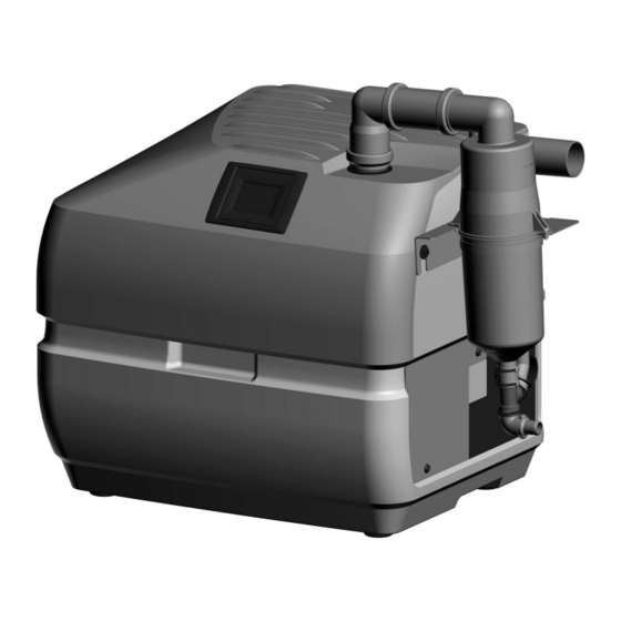
Product description Product description Overview Tyscor V 4 suction unit Condensation separator Mains cable with local mains plug Hose LW 50, 1.5 m Hose LW 50, 0.6 m Waste water hose LW 20 Set of connection fittings 7188100023L02 2109V004... -
Page 10: Scope Of Delivery
Tyscor V 4 ....7188100200 Tyscor V 4 ....7188200200 –... -
Page 11: Technical Data
Product description Technical data Electrical data 7188100200 7188200200 Rated voltage 230, 1~ 230, 1~ Mains frequency 50 / 60 50 / 60 Nominal current Rated power Fuses 2x T 10.0 AH / 250 V~ (IEC 60127-2) Type of protection IP 21 Protection class Control connection electrical data Output:... -
Page 12: Characteristic Curves
Product description Network connection Standard IEEE 802.3u Data rate Mbit/s Connector RJ45 Type of connection Auto MDI-X ³ CAT5 Cable type Ambient conditions during storage and transport Temperature °C -10 to +60 Relative humidity < 95 Ambient conditions during operation Temperature °C +10 to +40... - Page 13 Product description Fig. 2: Characteristic curves for: 7188200200 Normal litres in accordance with ISO 10637 7188100023L02 2109V004...
-
Page 14: Type Plate
Product description Type plate The type plate can be found on the housing lower part. Type plate Evaluation of conformity This device has been subjected to conformity acceptance testing in accordance with the cur- rent relevant European Union guidelines. This equipment conforms to all relevant requirements. -
Page 15: Operation
Product description Operation Suction connection on condensation separator Network connection Mains connection (power plug) Connection to amalgam separator (appliance power inlet) CAN bus Condensation drain Exhaust air connection Yellow LED – Ethernet Red LED – fault Green LED – ready for operation Blue LED –... -
Page 16: Condensate Separator
Product description Condensate separator The condensate separator collects any condensate that occurs in the pipe system and directs it to the outside. Radial blower The air that has been separated from the fluids is sucked into the radial blowers. The motors in the radial blowers are regulated on a demand-driven basis by the unit electronics. - Page 17 Product description When grouped together, mutual controlling and exchange of information takes place via the CAN bus. Only one device is permitted to be configured as the main unit; additional devices must be configured as auxiliary units. Overview of the touch screen user interface Display window Context range (e.g.
-
Page 18: Assembly
Assembly The following materials must not be used: Assembly – Acrylonitrile-butadiene-styrene (ABS), – Styrene copolymer blends (e.g. SAN + PVC). Requirements Hose materials The unit can be installed on the same level as the For waste connections and suction lines only use the following hose types: surgery room or in a floor below. -
Page 19: System Components
Assembly System components Installation type Line layout (minimum requirements) The system components listed below are Flexible – PVC data cable with required or recommended for various procedures shielded cable sheath- or for installation. ing, as used for tele- Exhaust air filter / bacteria fil- communications and IT processing systems (e.g. -
Page 20: Installation
Assembly Installation The actual connection can vary depend- ing on the chosen installation option. The connection shown is only an example. Mounting the condensate separator Attach the condensation separator to the ❯ holder with two screws. Fit the double sleeve with integrated protective ❯... -
Page 21: Installation And Routeing Of Hoses
Assembly Installation and routeing of hoses and pipes Establish connections between the pipe system and the unit using the flexible hoses supplied. This ❯ will prevent vibrations from being transmitted to the pipe system. The connection between the pipe line and unit suction connection should be kept as short as possi- ❯... -
Page 22: Installing The Group Of Devices
Assembly CAN bus Installing the group of devi- Purpose of the CAN bus connection In a grouping of up to three devices, the CAN To install the devices and combine them as a bus is used to enable mutual controlling and group, use the Installation Kit Tyscor V/VS Tan- information exchange between the devices. -
Page 23: Pcb (Main Board) Electrical Con- Nections
Assembly PCB (main board) electrical connections X14 X13 X15 X16 Supply voltage 230 V Control voltage output, 24 V DC, control voltage input Voltage supply for the rinsing unit, 24 V DC SD card holder (for Micro SD) CAN bus Service interface Connection for the display Supply voltage for suction motor 1... - Page 24 Assembly Green LED – voltage supply +5 V Green LED – HV voltage supply +15 V Green LED – HV voltage supply +5 V Green LED – HV voltage supply +3.3 V Green LED – temperature indicator for radial blower 1, temperature OK H10 Yellow LED –...
-
Page 25: Testing Suction Power After
Assembly Commissioning Testing suction power after installation In many countries technical medical prod- ucts and electrical devices are subject to The following procedure is recommended in regular checks at set intervals. The owner order to measure the maximum negative pres- must be instructed accordingly. - Page 26 Assembly In the display screen, use the Settings button to Setting the afterrun delay time switch to the menu screen. Use the Access Depending on the installation, the lag time of the Level button to switch to the selection for User, device can be adjusted.
-
Page 27: Monitoring The Unit Via The Network
Assembly Exhaust air filter Combining devices safely If an exhaust air filter is used, this will need to be – The overall safety of the unit and its main per- set up in the controller. This is the only way to formance features are independent of the net- ensure that a corresponding maintenance mes- work. -
Page 28: Usage
Usage 10.5 Fault Usage Red display flashes – Fault/failure of a radial blower RED LED illuminates 10 LEDs – Failure of both radial blowers – Failure of separation (VS only) Yellow LED – network Red LED – fault Green LED – ready for operation Blue LED –... -
Page 29: Overview On The Touch Screen
Usage 11 Overview on the touch To access the individual menu items, tap the rele- vant button. If there are multiple pages, the arrow screen buttons are used to scroll through the pages. The buttons at the bottom edge of the screen can be used to switch between the different menus. -
Page 30: 12 Disinfection And Cleaning
Usage 12 Disinfection and cleaning Notice Operation of the device restricted NOTICE Fault Device malfunctions or damage due to use of incorrect media Operation of the device interrupted Guarantee claims may become invalid as a result. Do not use any foaming agents such ❯... -
Page 31: Once Or Twice A Week Before The Midday Break
Usage The following are required for disinfection/clean- ing: ü Non-foaming disinfectant/cleaning agent that is compatible with the materials. ü Unit care system, e.g. OroCup To pre-clean, suck up 2 litres of water with the ❯ care system. Aspirate the disinfection/cleaning agent with ❯... -
Page 32: Maintenance
Usage 13 Maintenance All maintenance work must be performed by a qualified expert or by one of our Service Techni- cians. WARNING Infection due to contaminated unit Clean and disinfect the suction before working on the unit. ❯ Wear protective equipment when working (e. g. impermeable gloves, protective goggles and ❯... -
Page 33: Cleaning The Protective Strainer
Usage 13.1 Cleaning the protective strainer Loosen two screws on the condensation sepa- ❯ rator. Lift the condensation separator and pull it out ❯ of the double sleeve. Turn the double sleeve slightly to the side and ❯ hang the condensation separator on the screws. -
Page 34: Troubleshooting
Troubleshooting Troubleshooting 14 Tips for operators and service technicians Any repairs exceeding routine maintenance may only be carried out by qualified personnel or our service. WARNING Infection due to contaminated unit Clean and disinfect the suction before working on the unit. ❯... - Page 35 Troubleshooting Error Possible cause Remedy Suction performance too low Leak in the suction pipe Check and if necessary ❯ establish leak-tightness of suction pipe and connec- tions. * One radial blower defective Replace the radial blower. * ❯ Membrane valve defective Check the membrane valve at ❯...
-
Page 36: Error Messages
Troubleshooting 14.2 Error messages Error messages are displayed on the touch screen. If there is a network connection, the mes- sages can be forwarded to the monitoring software. If the device is not connected to the net- work, the messages can be read via a terminal client (e. g. PuTTY). Error Possible cause Remedy... - Page 37 Troubleshooting Error Possible cause Remedy Internal board communication Failed firmware update Perform/repeat the firmware ❯ update. * disturbed Control error Replace electronics. * ❯ Unexpected re-initialization Firmware error Perform/repeat the firmware ❯ update. * Short circuit to earth Radial blower motor defective Replace radial blower.
- Page 38 Troubleshooting Error Possible cause Remedy No main control unit detected. No main unit found. Check the Configure one device as the ❯ system. main unit. * Check system. Auxiliary unit has error. Fault on auxiliary unit Check the fault on the affec- ❯...
-
Page 39: Transporting The Unit
Troubleshooting 15 Transporting the unit WARNING Infection due to contaminated unit Disinfect the unit before transport. ❯ Close all media connections. ❯ Wear protective equipment to avoid any risk of infection (e.g. liquid-tight protective gloves, protective goggles, face mask). Before disassembly, clean and disinfect the ❯... -
Page 40: Appendix
Appendix Appendix 16 Menu structure Start screen Operating mode, vacuum Performance, tem- perature Settings Access level Operator Administrator Service Technician XXXXXX [PIN] Device information Device data Firmware File Library version PCB_SN Device usage data Operating hours Number of starts System settings Language Deutsch, Eng- lish, . - Page 41 Appendix Settings (con- Cluster settings Main unit Parameters tinued) Auxiliary unit 1 Auxiliary unit 2 XX s Lag time Quick Start Start / stop Eco Stop Exhaust air filter Present Control strategy Adaptive operation / parallel operation options List of alarms Alarm information Message history Maintenance...
-
Page 42: Handover Record
Appendix 17 Handover record This document confirms that a qualified handover of the medical device has taken place and that appropriate instructions have been provided for it. This must be carried out by a qualified adviser for the medical device, who will instruct you in the proper handling and operation of the medical device. Product name Order number (REF) Serial number (SN) - Page 44 Hersteller / Manufacturer: DÜRR DENTAL SE Höpfigheimer Str. 17 74321 Bietigheim-Bissingen Germany Fon: +49 7142 705-0 www.duerrdental.com info@duerrdental.com...
Need help?
Do you have a question about the Tyscor V 4 and is the answer not in the manual?
Questions and answers