
Related Manuals for Durr Dental VSA 300 S


Summary of Contents for Durr Dental VSA 300 S
- Page 1 VSA 300 S Installation and operating instructions 0297 9000-606-31/30 *9000-606-31/30*...
-
Page 3: Table Of Contents
Contents Contents Use of nitrous oxide ..Pipe materials ....Hose materials ....Important information Installation and routeing of hoses About this document . - Page 4 Contents 12.3 Amalgam collector vessel is 100% full ....12.4 Amalgam collector vessel not in position ....12.5 Motor fault .
-
Page 5: Important Information
Risk of minor injuries These installation and operating instructions – NOTICE apply to: Risk of extensive material/property damage VSA 300 S REF: 7125-01; 7125-01/002; 7125-01/021; Other symbols 7125-03; 7125-03/002; 7125-04/002 These symbols are used in the document and on or in the unit: Warnings and symbols Note, e.g. -
Page 6: Copyright Information
Important information Safety Medical device Dürr Dental has designed and constructed this unit so that when used properly and for the inten- Health Industry Bar Code (HIBC) ded purpose it does not pose any danger to people or property. Manufacturer Despite this, the following residual risks can remain: –... -
Page 7: Systems, Connection With Other Devices
Important information Cleaning and disinfection with agents contain- Installation and repairs ❯ ing sodium hypochlorite or potassium hypo- Installation, readjustments, alterations, ❯ chlorite. upgrades and repairs must be carried out by Assembly in a manner that does not comply Dürr Dental or by qualified personnel specifi- ❯... -
Page 8: Only Use Original Parts
Important information 2.10 Transport NOTICE The original packaging provides optimum protec- Negative effects on the EMC due to tion for the unit during transport. non-authorised accessories If required, original packaging for the unit can be Use only Dürr Dental parts or accesso- ❯... -
Page 9: Product Description
Orotol plus (2.5 litre bottle) ..CDS110P6150 VSA 300 S, 230 V AC, 50 Hz ..7125-01 MD 550 spittoon bowl cleaner VSA 300 S, 230 V AC, 50 Hz with (750 ml bottle) . -
Page 10: Technical Data
Product description Technical data Electrical data 7125-01 7125-03 7125-04 Rated voltage 230, 1~ 230, 1~ 230, 1~ Mains frequency Nominal current Starting current, approx. 10.4 10.4 Motor protection Motor winding overheat protector 160 °C (±5 °C) Rated power Type of protection IP 20 Protection class Protective low voltage... - Page 11 Product description General data Values without accessories and add-on parts Noise level in accordance with ISO 3746 Network connection LAN technology Ethernet Standard IEEE 802.3u Data rate Mbit/s Connector RJ45 Type of connection Auto MDI-X Cable type ³ CAT5 Ambient conditions during storage and transport Temperature °C -10 to +60...
- Page 12 Product description Electromagnetic compatibility (EMC) Interference immunity measurements cover Immunity to interference, high-frequency electromagnetic fields IEC 61000-4-3:2006+A1:2007+A2:2010 Compliant 3 V/m 80 MHz - 2.7 GHz 80 % AM at 1 kHz Immunity to interference from power frequency magnetic fields Compliant IEC 61000-4-8:2009 30 A/m at 50 Hz Immunity to interference, near fields of wireless HF com-...
- Page 13 Product description Electromagnetic compatibility (EMC) Interference immunity measurements supply input Immunity to interference, surges IEC 61000-4-5:2014/AMD1:2017 Compliant ± 0.5 kV, ± 1 kV, L - N ± 0.5 kV, ± 1 kV, ± 2 kV, L/N - PE Immunity to interference, line-conducted disturbances induced by high-frequency fields –...
-
Page 14: Type Plate
Product description Type plate The type plate is is located on the noise reduc- tion hood. Type plate Evaluation of conformity This device has been subjected to conformity acceptance testing in accordance with the cur- rent relevant European Union guidelines. This equipment conforms to all relevant requirements. -
Page 15: Operation
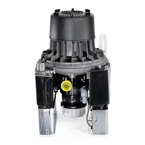
Product description Operation Motor Inlet connection with protective coarse filter Auxiliary air nozzle Waste water connection Amalgam collecting container Control electronics Exhaust air muffler Exhaust air connection Rotational speed sensor The mixture of liquids, solid particles and air drawn in passes through the inlet connection and into the suction unit. - Page 16 Product description The fluid and solids accreting in the separation chamber are continuously fed to the amalgam centri- fuge, where the amalgam particles are removed. The fluid extracted via the centrifuge is fed through the waste water valve and the outlet connection into the central waste-water system. Under the centrifuge there is an interchangeable collecting container into which the separated amalgam particles fall once the motor is switched off.
-
Page 17: Assembly
Assembly components in the system are also suitable for Assembly this purpose. Those responsible for setting up the system must assess this and approve and release the system for the aspiration of nitrous Requirements oxide. Operation with nitrous oxide is only per- The unit can be installed on the same level as the mitted if the exhaust air is transported surgery room or in a floor below. -
Page 18: Information About Electrical Connections
Assembly Lay the hose installation of the drains to or ❯ Installation type Line layout (minimum from the unit at a sufficient incline. requirements) If incorrectly laid, the hoses can Flexible – PVC flexible line become blocked with sedimentation. (e.g. H05 VV‑F) –... -
Page 19: System Components
In the absence of a spittoon or rinsing unit in the treatment unit, it is absolutely essential that a rinsing unit be installed in the VSA 300 S. In addi- tion, for surgical procedures and for procedures using airflow a rinsing unit must always be instal- led in the treatment unit to supply a small amount of water to the system during aspiration. -
Page 20: Installation
Assembly Installation The actual connection can vary depending on the chosen installation option. The connection shown is only an example. Installation and routeing of hoses and pipes Establish connections between the pipe system and the unit using the flexible hoses supplied. This ❯... - Page 21 Assembly Hose connector Æ 30 mm Hose clip 25-40 mm Waste air pipe (aluminium)Æ 30 mm inside Elbow DN 30 O-ring Æ 30x2 mm Securing ring Connector Æ 36 mm (external) O-ring Æ 20x2 mm Securing ring Hose sleeve Æ 20 mm Hose clamp Æ...
-
Page 22: Rinsing Unit Water Connections
Assembly Alternatively, attach the water hose with ❯ Rinsing unit water connec- adapter piece, seal, R3/4" screw connection, tions sleeve piece, double-tapered ring and locking nut to a water tap. Check the water pressure for the rinsing unit. The water pressure should be between 2 and 5 bar. -
Page 23: Electrical Connections
Assembly Electrical connections Connect the control line. ❯ Connection the display panel. ❯ Connect the network cable (optional when using monitoring software). ❯ Establish the electrical connection to the supply network (230 V). ❯ SD Socket T3,15AH H3 H2 (24V AC) (24V AC) Start U1/Z2... - Page 24 Assembly Sediment sensor lifting magnet H11 Network H12 Network 9000-606-31/30 2101V005...
-
Page 25: Connections And Displays Of The Control
Assembly Connections and displays of the control H3 H2 Voltage supply for the rinsing unit 24V output voltage and switching contact to suction unit in the treatment unit Display panel Sediment sensor light barriers Sediment sensor lifting magnet Collecting container safety switch Motor connection Mains connection Network connection... -
Page 26: Display Panel Connection
Connect the network cable in the network ❯ – Transmit data for archiving socket to the VSA 300 S in the network bush- – Provide documents concerning the units ing (X13). Plug in the network cable at the network con- ❯... -
Page 27: Commissioning
Assembly Commissioning Combining devices safely – The overall safety of the unit and its main per- In many countries technical medical prod- formance features are independent of the net- ucts and electrical devices are subject to work. The device is designed for operation regular checks at set intervals. - Page 28 Assembly Port Purpose Service 502 TCP Unit data Event protocol data Syslog 22 TCP, Diagnosis Telnet, 23 TCP 123 UDP Time The port can vary depending on the con- figuration. 9000-606-31/30 2101V005...
-
Page 29: 10 Service Program
Assembly 10 Service program 9000-606-31/30 2101V005... -
Page 30: Description Of The Service Program
Assembly Every time the service key is pressed, the sedi- 11 Description of the service ment level is checked. If a test container is used, the different 95% and 100% filling level on the program display panel can be revealed. Wear protective equipment to avoid any 11.4 Motor start - motor braking... -
Page 31: Usage
Usage 12.3 Amalgam collector vessel is Usage 100% full Yellow LED lights up 12 Display/handling Red display flashes Audible signal melody sounds – At a fill level of 100% the signal melody can no longer be switched off by pressing the reset button. -
Page 32: Brake Monitoring
Usage 13 Disinfection and cleaning If this problem happens again on the same day, the amalgam separator will no longer be operational - notify the service NOTICE technician. Device malfunctions or damage due to use of incorrect media 12.6 Brake monitoring Guarantee claims may become invalid as a result. -
Page 33: Once Or Twice A Week Before The Midday Break
Usage The following are required for disinfection/clean- 14 Replace the amalgam col- ing: lector vessel ü Non-foaming disinfectant/cleaning agent that is compatible with the materials. NOTICE ü Unit care system, e.g. OroCup Risk of contamination if the amalgam To pre-clean, suck up 2 litres of water with the ❯... -
Page 34: 15 Maintenance
Usage 15 Maintenance All maintenance work must be performed by a qualified expert or by one of our Service Techni- cians. WARNING Infection due to contaminated unit Clean and disinfect the suction before working on the unit. ❯ Wear protective equipment when working (e. g. impermeable gloves, protective goggles and ❯... -
Page 35: Tests
Usage Work steps to be performed: 15.1 Tests Remove the collector vessel. Here, the red ❯ LED on the display panel must flash and an WARNING audible signal must sound. Infection due to contaminated unit Insert the test collector vessel. ❯... -
Page 36: Troubleshooting
Troubleshooting Troubleshooting 16 Tips for operators and service technicians Any repairs exceeding routine maintenance may only be carried out by qualified personnel or our service. WARNING Infection due to contaminated unit Clean and disinfect the suction before working on the unit. ❯... - Page 37 Troubleshooting Error Possible cause Remedy Suction performance too low Coarse filter blocked Clean the coarse filter at the ❯ intake connection. Leak in the suction line Check and if necessary ❯ establish leak-tightness of suction system and connec- tions. * Mechanical sluggishness of tur- Disassemble the unit and ❯...
-
Page 38: 17 Transporting The Unit
Troubleshooting 17 Transporting the unit WARNING Infection due to contaminated unit Disinfect the unit before transport. ❯ Close all media connections. ❯ Wear protective equipment to avoid any risk of infection (e.g. liquid-tight protective gloves, protective goggles, face mask). Before disassembly, clean and disinfect the ❯... -
Page 39: Appendix
Appendix Appendix 18 Handover record This document confirms that a qualified handover of the medical device has taken place and that appropriate instructions have been provided for it. This must be carried out by a qualified adviser for the medical device, who will instruct you in the proper handling and operation of the medical device. Product name Order number (REF) Serial number (SN) - Page 40 Appendix 9000-606-31/30 2101V005...
- Page 44 Hersteller / Manufacturer: DÜRR DENTAL SE Höpfigheimer Str. 17 74321 Bietigheim-Bissingen Germany Fon: +49 7142 705-0 www.duerrdental.com info@duerrdental.com...
Need help?
Do you have a question about the VSA 300 S and is the answer not in the manual?
Questions and answers