
Related Manuals for Durr Dental VC 45


Summary of Contents for Durr Dental VC 45
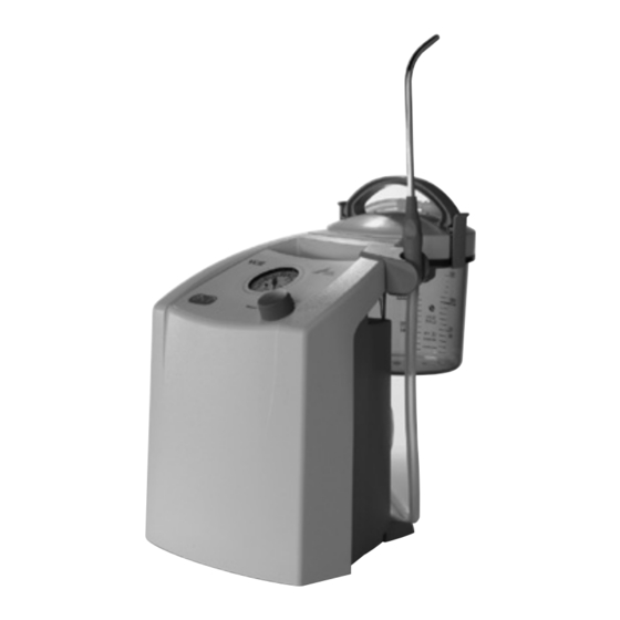
- Page 1 VC 45 Surgical Suction Unit Installation and Operating Instructions 0297 9000-606-70/30 ...
-
Page 3: Table Of Contents
16�2 Removing the container � � � � � � � � � 22 5�1 Suction Unit VC 45 � � � � � � � � � � � � � � 8 16�3 Disinfection and cleaning � � � � � � � � 22 6. -
Page 4: Important Information Use
quoted are protected under industrial property Important rights� Information • The translation of these Installation and Oper- ating Instructions has been carried out in good faith� No liability can be accepted for 1. General mistakes in the translation� The enclosed Ger- man version of these Installation and Operat- 1.1 Evaluation of conformity ing Instructions is the reference version�... -
Page 5: 1�5 Notes On Emc For Medical Products
• Before every use, the operator must check 1.6 Correct Usage the functional safety and the condition of the This surgical suction unit VC 45 is a specially appliance� designed suction unit for use in dental medical • The operator must be familiar with the opera- fields or clinics and for use in surgeries or other tion of the appliance�... -
Page 6: Warnings And Symbols
3. Warnings and Symbols The following terminology and symbols are used in these Installation and Operating Instructions to denote especially important information: Information and/or mandatory regu- lations or prohibitions for the pre- vention of personal injury or sub- stantial property damage. Information and/or instructions or prohi- bitions regarding personal safety or ex- tensive material damage... -
Page 7: Overview
� � � � � � � � � � � � � � � � � � � 0670-981-01 VC 45 ..... . 0670-01/001 Collector, 1�5 litres �... -
Page 8: Technical Data
(hPa) max� -910 supply switch, the vacuum pump in the unit Weight 6�7 starts up� On the upper side of the VC 45 there Dimensions WxHxD cm 24x33x36 is a pressure gauge which displays the level of with cart... -
Page 9: Installation
7.2 Set-up alternatives • Set up the VC 45 on a stable flat and raised surface next to the treatment unit� Operation of the VC 45 directly on the floor is not permitted • Set up the VC on the special cart (available as... -
Page 10: Preparation For Usage
9. Preparation for usage • Place the splash protector (13) onto the filter housing in the collector lid� • The collector lid (14) must be set up vertically on top of the collector which must itself be on an absolutely level surface� • Press the cover carefully down using both hands until the cover engages�... - Page 11 • Slide the collector vessel handle (16) with locking hooks (17) in the open position into the guide on the cover� • Hang the locking clip (1) under the lip of the collector vessel and press the upper end (2) in the direction of the middle of the collector until it locks into place�...
-
Page 12: Operating The Appliance
• Now place the collector vessel vertically downwards into the retaining clip mouldings on the basic unit� • Hang the handpiece holder (24) into position on the basic unit� • Place the suction handpiece into the hand- piece holder� When ready to use the appliance, insert the suction cannula into the cannula retainer piece on the suction handpiece�... -
Page 13: 10�2 Adjusting The Vacuum
10.2 Adjusting the vacuum • Close the suction hose and use the pressure regulator (26) to set the max� vacuum using the arrow markings� Do not use excessive force to rotate the vacuum setting against the closed position. If the desired vacuum cannot be ac- quired, check the system for any signs of leaks;... -
Page 14: Disposable Bag
on the vacuum setting with an open suction hose shows more than 0�3 bar� 11. Disposable bag Use of the disposable bags when using the VC 45 table mounted� • Place the standard guide adapter (40) onto the basic unit from above� • Secure the standard adapter from below us- ing two screws (41) and flat washers�... -
Page 15: 11�1 Disposable Bag With Gelling Agent
• The elbow piece (50) must now be inserted into the disposable bag� • Switch on the VC 45, close the connector piece and simultaneously apply slight pressure to the middle of the cover of the disposable bag� Briefly wait until the bag has completely unfolded�... -
Page 16: Foot Switch
12.2 Foot switch function The foot switch operates pneumatically and has no electrical connection to the VC 45� • The unit operating switch (25) for foot pedal operation must be switched to the OFF posi- tion� The unit is started via an internal switch�... -
Page 17: Vc Cart
13. VC Cart For OP operation, a special VC Cart is available as a special accessory� 13.1 Fixture of suction unit Safe operation as a mobile suction sys- tem can only be ensured where the ap- pliance is used in combination with the specially prepared VC Cart�... -
Page 18: Disposable Bag
14. Disposable bag Using the disposable suction bag on the VC Cart� • Place the standard guide adapter (40) onto the basic unit from above� • Secure the standard adapter from below us- ing two screws (41) and flat washers� • Fix the screws (42), spacers and nuts in place on the adapter�... - Page 19 • The elbow piece (50) must now be inserted into the disposable bag� • Switch on the VC 45, close the connector piece and simultaneously apply slight pressure to the middle of the cover of the disposable bag� Briefly wait until the bag has completely unfolded�...
-
Page 20: Dispose Of The Disposable Bags And Suction Hoses
Connect the connection hose (53)� • The elbow piece (50) must now be inserted into the disposable bag on the left� • Switch on the VC 45, close the elbow piece and simultaneously apply slight pressure to the middle of the cover of the disposable bag�... -
Page 21: Preparation
VC 45 compo- Risk assessment and classification nents after every use is in accordance with the The VC 45 is a medical product that comes into preparation information according to contact with blood and internal tissues�... -
Page 22: 16�2 Removing The Container
16.2 Removing the container • Lift the complete container vertically upwards with one hand firmly holding the handle and guide� With the other hand on the base of the collector, guide the collector vessel upwards so that it does not tilt while being lifted out� • Release the engaging catches of the handle to the collector�... -
Page 23: 16�4 Steam Sterilising
16.4 Steam sterilising Individual parts can be sterilised either un- packed or packed in a container or in sterile product packaging� Use suitable sterile product packaging� Warning Incorrect sterilisation inhibits effec- tiveness and can damage the product • Only steam sterilisation is permitted� • Do not exceed 134 °C�... -
Page 24: 16�5 Checking And Testing The Functioning
16.5 Checking and testing the functioning Frequent reprocessing in this way can have a slight effect on plastic and rubber parts, such as collector, collector lid, handle and suction hose� The end of the product's life cycle is determined by the amount of wear and tear or damage dur- ing use�... -
Page 25: Maintenance
17. Maintenance The bacteria filter/excess suction stop (15) is only to be used once and must be changed at least once a day� If the appliance is to be used continu- ously for longer periods (several hours), it is important to change the bacteria fil- ter after each patient�... -
Page 26: Troubleshooting
Troubleshooting 19. Tips for Operators and Service Technicians Any repairs above and beyond routine maintenance must be carried out by suitably qualified personnel or one of our service technicians. Before any service, unplug at the mains and remove all power. Problem Probable cause Solution... - Page 28 Hersteller/Manufacturer: DÜRR DENTAL SE Höpfigheimer Str. 17 74321 Bietigheim-Bissingen Germany Fon: +49 7142 705-0 www.duerrdental.com info@duerrdental.com...
Need help?
Do you have a question about the VC 45 and is the answer not in the manual?
Questions and answers