
Subscribe to Our Youtube Channel
Related Manuals for Durr Dental Vector Paro


Summary of Contents for Durr Dental Vector Paro
- Page 1 Vector Paro / Vector Paro Pro Installation and operating instructions 0297 9000-615-28/02 *9000-615-28/02*...
-
Page 3: Table Of Contents
Overview ......Vector Paro / Vector Paro Pro . . . Service kit .... - Page 4 Contents 12.2 Activating the cleaning process 15.9 Changing the support seal ..of the device ....15.10 Checking the function of the tool 12.3 Cleaning the fluid container .
-
Page 5: About This Document
Important information Important information Comply with the Operating Instructions. About this document Protection class II These installation and operating instructions rep- resent part of the unit. CE labelling with the number of the noti- If the instructions and information in these fied body installation and operating instructions are not followed, Dürr Dental will not be able... -
Page 6: Copyright Information
Important information Amplitude increase Switch off and de-energise the unit (e.g. unplug from mains). Wear protective gloves. Wear protective goggles. Use a face mask. Use protective clothing. Rinse with water. Rinse with instrument cleaner. Rinse with instrument disinfectant. Copyright information All circuits, processes, names, software pro- grams and units mentioned in this document are protected by copyright. -
Page 7: Safety
Important information Safety Improper use Dürr Dental has designed and constructed this WARNING unit so that when used properly and for the Risk of explosion due to ignition of intended purpose it does not pose any danger to combustible materials people or property. -
Page 8: Electrical Safety
Important information Only use original parts Installation and repairs Installation, readjustments, alterations, ❯ Only use Dürr Dental parts or accessories and ❯ upgrades and repairs must be carried out by special accessories specifically approved by Dürr Dental or by qualified personnel specifi- Dürr Dental. -
Page 9: Disposal
Important information Disposal Unit The unit must be disposed of properly. Within the European Union, the unit must be disposed of in accordance with EU Directive 2012/19/EU (WEEE). If you have any questions about the correct ❯ disposal of parts, please contact your dental trade supplier. -
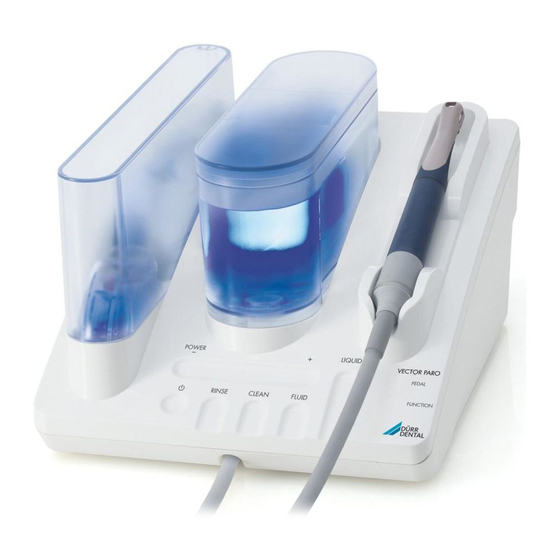
Page 10: Overview
Product description Product description Overview Vector Paro / Vector Paro Pro 9000-615-28L02 1903V004... - Page 11 Product description P1 - P4 P1 P2 P3 P4 Piercing mechanism for the fluid bag 12 Paro tool kit (blue ring) Fluid-bag "Vector Fluid Polish" 13 Recall/Implant tool kit (black ring) Cover for fluid bag 13a Instruments for peri-implantitis treatment, Cover for fluid container peri-implant soft and peri-implant hard Fluid container...
- Page 12 ......2032100008 Vector Paro ..... . 2031-50 Instruments for Paro handpiece –...
-
Page 13: Wear Parts And Replacement
Product description Wear parts and replacement parts The following working parts need to be changed at regular intervals (refer to the "Maintenance" section): Instruments for Paro handpiece and Scaler hand- piece, see "3.3 Accessories" Service kit ....2031-340-00 Light conductor for Scaler hand- piece (4 pcs.) . -
Page 14: Technical Data
Product description Technical data Electrical data – power supply unit Rated voltage V AC 100 - 240 Mains frequency 50 - 60 Rated power Current consumption 1 - 0.5 Protection class Type of protection IP 20 Electrical data – basic unit and handpieces Voltage V DC Electrical power ON... -
Page 15: Operation
Product description Battery for flexible foot switch Voltage Type Lithium CR2032 Ambient conditions during transport and storage Temperature °C -15 to +60 Relative humidity Max. 95 Ambient conditions during operation Temperature °C +10 to +40 Relative humidity Max. 80 Electromagnetic compatibility (EMC) Interference emission measurements High-frequency emissions in accordance Group 1... - Page 16 Product description Type plate The type plate is located on the rear of the device. Paro handpiece Scaler handpiece ID number for tool kits The seal is located on the base of the device. There is an ID number on the Paro and Recall/ Implant tool kit covers and on the Scaler tool kits.
-
Page 17: Requirements
Product description Evaluation of conformity Operation This device has been subjected to conformity Handpieces acceptance testing in accordance with the cur- rent relevant European Union guidelines. This During treatment using the Paro or Scaler hand- equipment conforms to all relevant requirements. pieces, they can be operated using just water or using water and Vector Fluid Polish as required. - Page 18 Product description Instrument change A torque wrench is required for inserting/chang- ing the instruments. This is integrated in the tool kit cover for the instruments of the Paro hand- piece. For the instruments of the Scaler hand- piece there is a separate torque wrench. 9000-615-28L02 1903V004...
-
Page 19: Installation
Assembly Installation Assembly Establishing the electrical connections Requirements The connection ports are located in the recess The room chosen for installation must satisfy the on the rear of the unit. following requirements: Requirements: – Closed, dry room ü Correctly installed power outlet in the vicinity of –... -
Page 20: Nections
Assembly Connecting the flexible foot In order to avoid interference in wireless switch operation, we recommend that a maxi- mum of 4 flexible foot switches is used The flexible foot switch can be operated wirelessly within a single surgery. using a foot switch cable or wirelessly. If interference does occur during wireless operation, we recommend using the flexi- LED PEDAL flashes in orange after the unit is... -
Page 21: Commissioning
Assembly Commissioning Performing pairing between the flexible foot switch and the device: Switch on the device ❯ Function check To finish the initial start-up process, all of the POWER LIQUID connections must be checked to make sure they PEDAL are securely seated and leak-tight. FUNCTION RINSE CLEAN... -
Page 22: Paro Handpiece
The power is adjusted in the POWER operating If a handpiece is damaged by dropping panel. it, this can cause injuries and may result The Vector Paro handpiece enables optimum in an unsuccessful treatment. adjustment of the ultrasonic power according to Perform a visual inspection for cracks ❯... - Page 23 Usage Press the ring cover carefully against the clip Press the ring cover downwards until it the clip ❯ ❯ closure to detach it and then remove. closure engages. Twist the rotary adaptor anti-clockwise and Connect the hose connection at the hand- ❯...
-
Page 24: Paro Handpiece
Usage Start the handpiece with the foot switch. ❯ During treatment using the Paro handpiece the nozzle ejects fluid as a pulsating stream. The fluid hits the instrument in the top third. Possible faults: – If spray mist is released there is possibly air in the hose lines. -
Page 25: Scaler Handpiece
Usage Before every treatment check that the sealing The cooling channel runs to a point just before ❯ rings are in place and that they are intact. Miss- the instrument tip. This offers the following ing or defective sealing rings must be replaced advantages: immediately. -
Page 26: Instruments And Tool Kits
Usage Assembly LED dis- Water amount play 45 ml/min Illumination Power Connect the light conductor. ❯ Screw the front cover onto the handpiece ❯ working clockwise. Connect the hose connection at the hand- ❯ piece. Instruments and tool kits Overview Instruments of various shapes, lengths and mate- rials are available. - Page 27 Usage Paro tool kit The Paro tool kit contains instruments for the Vector Paro handpiece for initial periodontal treat- ment. 14 Scaler tool kit torque wrench with integrated PREMIUMLINE instrument 15 Torque wrench for all PREMIUMLINE instru- ments (P1 - P4)
- Page 28 Recall/Implant tool kit Scaler tool kit The Recall/Implant tool kit contains instruments The use of metal instruments enables a higher for the Vector Paro handpiece. application of energy. Application areas: – Periodontal initial treatment – Removal of concrement and dental tartar PREMIUMLINE instruments Each instrument is contained in its own tool kit.
-
Page 29: Flexible Foot Switch
Usage Steri-box Paro steri-box (cover: silver) The rubber clips on the carrier plate can be replaced if necessary. Flexible foot switch The handpieces are operated with the flexible foot switch. Scaler steri-box (cover: blue) In wireless operation the flexible foot switch is supplied with voltage from a battery. -
Page 30: Service Kit
Usage Service kit Water quality The water quality must meet the general require- ments for water supply systems in a dental surgery and all applicable standards. Active ingredient solutions NOTICE Blockage of the nozzle when mixing water-based active ingredient solu- tions with Vector Fluid Polish. -
Page 31: Vector Toolcard
Usage Vector cleaner CAUTION Ready-to-use solution for the removal of acid- Extremely sensitive patients may soluble deposits in the hose system and in the experience reactions on their mucous handpieces of the Vector system. Special cleaner membranes. with intensive cleaning effect and very good material compatibility. -
Page 32: Operation
Usage 10 Operation If no function is used for a period of 30 minutes, the unit will automati- 10.1 Display/handling cally switch off (standby). POWER (power setting) Paro handpiece inserted: POWER adjustment possible 1 – 5 LEDs light up depending on the power setting selected (5 LEDs LIQUID adjustment not possible = maximum power) -
Page 33: Adjustment Options
Usage 10.2 Adjustment options LED on: low battery power – change the battery of the flexible foot Operating panel switch. LED flashing: no flexible foot switch connected (cable operation) or POWER paired (wireless operation). LIQUID PEDAL FUNCTION FUNCTION RINSE CLEAN FLUID LED flashing: treatment was stopped. -
Page 34: Preparing The Device For Treat
Usage If the orange LED flashes then no flexible foot LIQUID switch is connected or paired. On the Scaler handpiece the water amount can be selected from 3 settings, which are displayed FUNCTION via 3 LEDs: If the orange LED lights up, the contact pressure LED dis- Water amount in ml/min of the instrument is too high or the handpiece... - Page 35 Usage Check that the rubber seal is correctly seated ❯ The closure of the fluid bag must not be in the device. The rubber seal must remain in removed. position in the device during operation. Insert the fluid bag in the correct position in the ❯...
-
Page 36: Treatment
Usage cally. If necessary the process can be stopped Inserting/changing instruments earlier by pressing the button again. CAUTION Inserting the fluid container If an attempt is made to perform a Check whether the fluid container is full. If nec- ❯ treatment with a damaged or worn essary top up the fluid container to the upper instrument, this can cause injury and... - Page 37 Usage Use the tool kit cover to tighten the union nut ❯ of the instrument chuck until the torque limit is reached and ratcheting of the tool kit cover can be heard. CLICK Instrument for Scaler handpiece: To prevent the instrument from being overtightened, the torque wrench slips when the required torque is reached.
-
Page 38: Preparation
Usage 11 Treatment 11.2 Treatment using the Paro handpiece 11.1 Preparation During treatment using the Paro handpiece fluid Perform the following steps before every treat- is applied as a pulsating jet. Once the flexible foot ment: switch is released a small amount of fluid will still Make sure that only handpieces and instru- ❯... - Page 39 Excess fluid should preferably be aspirated ❯ Always guide the Vector Paro instrument paral- ❯ using the smaller saliva ejector in the dorsal lel to the root surface. oral cavity area on the contralateral side.
-
Page 40: Treatment With A Scaler Hand
Usage 11.3 Treatment with a Scaler hand- NOTICE piece Residue of Vector Fluid Polish can cause blockages in the device. CAUTION Rinse the unit with water after every ❯ Risk of injury due to burns treatment in which Vector Fluid Polish During operation some of the compo- is used (RINSE). -
Page 41: Use Of The Scaler Instruments
Usage 11.4 Use of the Scaler instruments Application areas CAUTION Risk of injury Accidental activation or uncontrolled activities of the handpiece can cause injuries. Insert the handpiece in the handpiece ❯ holder when it is not in use. Dismantle the instrument or push on ❯... -
Page 42: After Every Treatment
Usage 12 Cleaning 12.1 Cleaning of the outside sur- faces All outside surfaces must be cleaned and disin- fected if they are contaminated or soiled. – Surface of the device – Handpiece hose – Protective cap of the fluid polish bag –... -
Page 43: Activating The Cleaning Process
Usage 12.2 Activating the cleaning pro- Pull off the hose connection from the hand- ❯ piece. cess of the device We recommend that cleaning is per- formed every 4 weeks. The cleaning pro- cess can be started at any time as required. - Page 44 Usage Pour 2 sealing caps (approx. 40 ml) of Vector RINSE (rinsing/disinfecting): ❯ cleaner undiluted into the empty fluid con- As a result of the rinsing with water the tainer. special cleaner Vector cleaner is removed from the system. Any residue of the cleaning agent could cause irritation in the patient.
-
Page 45: Cleaning The Fluid Container
Usage 12.3 Cleaning the fluid container 12.4 Cleaning the sleeve part and adapter of the handpiece The fluid container should regularly cleaned and descaled. hose How soon descaling is required depends primar- Pull off the handpiece hose from the hand- ❯... -
Page 46: Reprocessing
Usage 13 Reprocessing 13.2 Reprocessing procedure in accordance with EN ISO 13.1 Risk analysis and categorisa- 17664 tion The reprocessing procedure after each patient A risk analysis and categorisation of medical treatment is carried out according to the repro- products often used in dentistry must be per- cessing procedure established by EN ISO 17664. - Page 47 Usage The reprocessing method was validated as fol- Comply with all national directives, standards ❯ lows: and specifications for the cleaning, disinfection – Pre-cleaning and sterilisation of medical products as well as the specific specifications for dental practices – FD 350 disinfection wipes (Dürr Dental) and clinics.
-
Page 48: Preparation At The Operating Location
Usage 13.3 Preparation at the operating Start the rinsing process: ❯ Press the RINSE button for at least 2 seconds. location RINSE Wear protective gloves. Wear protective goggles. The LED flashes – the rinsing process takes ❯ around 30 seconds and ends automatically. Use a mask. -
Page 49: Dismantling The Handpiece
Usage 13.4 Dismantling the handpiece Cleaning Place the removable parts of the handpiece ❯ Unscrew the instrument, see "Inserting/chang- ❯ (ring cover, rotary adaptor, scaler cover, light ing instruments". conductor), instrument holders of the tool kits Take off the removable parts of the handpiece, ❯... - Page 50 Usage Rinse handpieces through at least 3 times Screw scaler instruments onto the rinsing ❯ ❯ using a 20-ml disposable pipette. adapter one after another and rinse through each of the instruments at least 3 times with water using a 20-ml disposable pipette. 20 ml 20 ml Screw Scaler instruments onto the rinsing...
- Page 51 Usage Rinse handpieces through at least 3 times Disinfection ❯ using a 20-ml disposable pipette. Place the removable parts of the handpiece ❯ (ring cover, rotary adaptor, scaler cover, light conductor), instrument holders of the tool kits (without instruments), torque wrench and the disassembled handpieces in the disinfection 20 ml bath for the required action time, so that all...
-
Page 52: Manual Cleaning, Intermediate Rinsing, Disinfection, Final Rinse
Usage 13.6 Manual cleaning, intermedi- Place instruments in small parts baskets into ❯ the ultrasonic bath. ate rinsing, disinfection, final rinse, drying in ultrasonic bath A combined cleaning and disinfectant agent is required for manual cleaning and disinfection. It must have the following properties: –... - Page 53 Usage Screw Scaler instruments onto the rinsing Areas that are difficult to reach, e.g. the ❯ ❯ adapter one after another and rinse through Paro handpiece instrument chuck, should be each of the instruments at least 3 times using a thoroughly rinsed (at least 5 x for 5 seconds 20-ml disposable syringe.
- Page 54 Usage Place instruments in small parts baskets into Screw Scaler instruments onto the rinsing ❯ ❯ the ultrasonic bath. adapter one after another and rinse through each of the instruments at least 3 times using a 20-ml disposable syringe. 20 ml Remove all rinse adapters.
-
Page 55: Automatic Cleaning, Intermediate Rinsing, Disinfection, Final Rinse, Drying
Usage Areas that are difficult to reach, e.g. the Place the handpiece on the special mountings ❯ ❯ Paro handpiece instrument chuck, should be for transmission instruments (e. g. Miele: ADS 2, Æ approx. 16 mm) in the washer-disin- thoroughly rinsed (at least 5 x for 5 seconds each) using an air and water syringe. -
Page 56: Packing
Usage 13.9 Packing NOTICE Damage to equipment due to incor- CAUTION rect sterilisation Endangering the sterilisation success If the sterilisation process is not per- The fitted components are not reached formed correctly, this can cause dam- by the steam and as such are not ster- age to the product. -
Page 57: Storing Parts For Sterilisation
Usage 13.12 Storing parts for sterilisation Comply with the stated storage conditions: ❯ – Store the parts protected against contami- nation – Dust-protected, e.g. in a locked cabinet – Protected against moisture – Protected against excessive temperature fluctuations – Protected against damage Packaging for a sterile medical device can suf- fer damage as a result of a particular incident and the passage of time. -
Page 58: Treatment Breaks For More Than 24 Hours
Usage 14 Treatment breaks for more Lay the handpiece hose in the sink. ❯ than 24 hours If no treatment is carried out for a period of 24 hours or more, reprocessing of the hose sys- tem must be performed. 14.1 Cleaning and disinfecting the hose system... -
Page 59: Initial Start-Up After A Break In Treatment For More Than
Usage Touch the RINSE (rinsing/disinfecting) button Fluid pre-delivery to the handpiece: ❯ ❯ for at least 2 seconds. Touch the FLUID button for at least 2 sec- onds. RINSE The LED flashes simultaneously with the LED in the piercing mechanism; the process ends automatically. -
Page 60: Maintenance
Usage 15 Maintenance 32 Flat wrench SW5 33 Nozzle torque wrench 34 Test tool, SW3.5, for torque wrench in the 15.1 Service kit tool kit cover The service kit has been configured for the 35 Sealing screw Vector System. 36 Rubber seal in piercing mechanism The service kit contains spare parts and tools, 37 O-Rings for valve in fluid container* which can be used for maintenance and repairs. -
Page 61: Changing The Valve In The Fluid Container
Usage 15.3 Changing the valve in the 15.4 Checking instrument wear fluid container Instrument wear can be checked using the Vector toolcard: The valve on the underside of the fluid container must be cleaned regularly and checked for blockages and leaks. –... -
Page 62: Replacing The Light Conductor In The Scaler Handpiece
Usage 15.5 Replacing the light conductor 15.6 Replacing the sealing screw in the Scaler handpiece The sealing screw in the adapter of the hand- piece hose must be replaced 1x per year. The light conductor must be checked regularly Unscrew the sealing screw: for light transmission. -
Page 63: Inserting Or Changing The Battery In The Flexible Foot Switch
Usage 15.7 Inserting or changing the bat- operation or if the power of the existing battery is low. tery in the flexible foot switch Opening the cover: A new battery should be inserted in the flexible Press both pins on the flexible foot switch ❯... - Page 64 Usage Fit the cover in such a way that the two pins ❯ on the side of the flexible foot switch snap into the holes in the cover. Inserting the battery: Insert the battery in the holder. Make sure ❯ that the battery is inserted with the correct polarity.
-
Page 65: Changing The Nozzle In The Paro Handpiece
Usage 15.8 Changing the nozzle in the New nozzles are stored in the nozzle Paro handpiece torque wrench housing. The nozzles are made of plastic and do Remove the instrument, "Inserting/changing ❯ not have a thread. The thread die in the instruments". -
Page 66: Changing The Support Seal
Usage Check the nozzle function with an instrument Carefully and completely remove the old or ❯ ❯ clamped in place. defective support seal from the union nut using a suitable tool. 15.9 Changing the support seal Place the assembly sleeve onto the union nut. ❯... -
Page 67: Checking The Function Of The Tool
Usage Place the test tool (included in the service kit) Result: ❯ The assembly pin is a disposable item and can vertically in the torque wrench. be disposed of after use. Disinfect the assembly sleeve with standard commercially available disinfectant, e.g. FD 322 or ID 212 forte. -
Page 68: Resonant Ring
Usage 15.11 Changing the sealing ring of Change the sealing ring of the resonant ring. ❯ the resonant ring Sealing ring, order number NOTICE Damage to the resonant ring due to twisting When loosening and tightening the nut ❯ do not hold down the resonant ring. Dismantle the handpiece, "Disassembly". -
Page 69: 15.12 Changing The Resonant Ring
Usage 15.12 Changing the resonant ring 15.13 Changing the interchangeable bushing with union nut Resonant ring, order number The interchangeable bushing (instrument chuck) NOTICE and union nut are subject to wear due to usage. Damage to the resonant ring due to They need to be replaced in the following cases: twisting –... - Page 70 Usage Place the adapter (contained in the service kit) Place the adapter in the hexagon socket of the ❯ ❯ in the hexagon socket of the tool kit cover and tool kit cover and tightly screw the interchange- unscrew the interchangeable bushing from the able bushing onto the resonant ring until the resonant ring.
- Page 71 Usage Take out the adapter from the tool kit cover ❯ and store it in the service kit. 9000-615-28L02 1903V004...
-
Page 72: Troubleshooting
Troubleshooting Troubleshooting 16 Tips for operators and service technicians Prior to working on the device or in case of danger, disconnect it from the mains (e. g. pull the mains plug). Any repairs exceeding routine maintenance may only be carried out by qualified personnel or our service. - Page 73 ❯ defective. Fluid is sprayed in pulses onto Normal operating status. NOT A FAULT. the instrument (Vector Paro The avoidance of spray mist and instrument warming means that handpiece). only a minimal quantity of liquid is required for cooling. Pulsed application of fluid is Fluid bag has not been pierced, Pierce the fluid bag;...
- Page 74 Troubleshooting Error Possible cause Remedy No fluid ejected from the noz- The nozzle in the Paro hand- Replace the nozzle in the Paro ❯ piece is blocked or defective. handpiece. zle of the Paro handpiece. Fluid container is empty. Fill the fluid container. ❯...
- Page 75 Troubleshooting Error Possible cause Remedy Instrument cannot be inserted Instrument chuck is deformed. Unscrew the union nut using ❯ the tool kit cover. or instrument is loose in the If the locking nut is tightened instrument chuck. using the torque wrench without Carefully widen the instrument ❯...
- Page 76 Troubleshooting Error Possible cause Remedy Orange "FUNCTION" LED The treatment was interrupted Clean the affected areas and ❯ as water may be present in the dry using the air and water lights up or flashes following areas: syringe. - between the handpiece and If necessary, tighten the union ❯...
- Page 77 Troubleshooting Error Possible cause Remedy The illumination in the Scaler The light conductor has become Replace the light conductor. ❯ opaque or has become milky. handpiece becomes increas- ingly dimmer. Illumination LEDs are defective. Send in the defective Scaler ❯ handpiece for repairs.
- Page 80 Hersteller/Manufacturer: DÜRR DENTAL SE Höpfigheimer Str. 17 74321 Bietigheim-Bissingen Germany Fon: +49 7142 705-0 www.duerrdental.com info@duerrdental.com...
Need help?
Do you have a question about the Vector Paro and is the answer not in the manual?
Questions and answers