Durr Dental Tyscor VS 4 Installation And Operating Instructions Manual
Hide thumbs
Also See for Tyscor VS 4:
- Installation and operating instructions manual (52 pages) ,
- Installation and operating instructions manual (56 pages)

Related Manuals for Durr Dental Tyscor VS 4


Summary of Contents for Durr Dental Tyscor VS 4
- Page 1 Tyscor VS 4 Installation and operating instructions 0297 7188100021L02 *7188100021L02*...
-
Page 3: Table Of Contents
Contents Contents Overview of the touch screen user interface ....Important information About this document ....Assembly Warnings and symbols . - Page 4 Contents 11 Overview on the touch screen ..11.1 "Home" screen ....11.2 "Settings" screen ... . . 11.3 "Messages"...
-
Page 5: Important Information
These installation and operating instructions apply to: Wear protective gloves. Tyscor VS 4 Order number: 7188100100 Disconnect all power from the unit. Warnings and symbols Warnings... -
Page 6: Copyright Information
Important information Safety Keep dry Dürr Dental has designed and constructed this unit so that when used properly and for the intended purpose it does not pose any danger to Keep away from sunlight people or property. Despite this, the following residual risks can remain: Stacking limits –... -
Page 7: General Safety Information
Important information The unit must not be used as a vacuum Specialist personnel ❯ cleaner. Operation Do not use chemicals containing chlorine or ❯ Unit operating personnel must ensure safe and foaming chemicals. correct handling based on their training and Operation in operating theatres of explosive ❯... -
Page 8: Transport
Important information Dürr Dental accepts no liability for dam- ages or injury resulting from the use of non-approved accessories or optional accessories, or from the use of non-origi- nal wear parts or replacement parts. The use of non-approved accessories, optional accessories or non-genuine wear parts / replacement parts (e.g. -
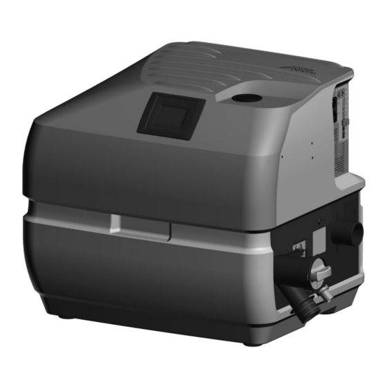
Page 9: Product Description
Product description Product description Overview Tyscor VS 4 combination suction unit Mains cable with local mains plug Hose LW 50, 1.5 m Hose LW 50, 0.6 m Waste water hose LW 20 Set of connection fittings 7188100021L02 1909V003... -
Page 10: Scope Of Delivery
(possible variations due to country-spe- cific requirements and/or import regulations): Tyscor VS 4 ....7188100100 – Combination suction unit – Mains cable –... -
Page 11: Technical Data
Product description Technical data Electrical data Rated voltage 230, 1~ Mains frequency 50/60 Nominal current Rated power Fuses 2x T 10.0 AH / 250 V~ (IEC 60127-2) Type of protection IP 21 Protection class Control connection electrical data Output: Voltage V DC Max. - Page 12 Product description General data Noise level * ca. dB(A) 61 / 64 Noise level in accordance with ISO 3746 Network connection LAN technology Ethernet Standard IEEE 802.3u Data rate Mbit/s Connector RJ45 Type of connection Auto MDI-X ³ CAT5 Cable type Ambient conditions during storage and transport Temperature °C...
-
Page 13: Type Plate
Product description Type plate The type plate can be found on the lower part of the housing. Type plate Evaluation of conformity This device has been subjected to conformity acceptance testing in accordance with the cur- rent relevant European Union guidelines. This equipment conforms to all relevant requirements. -
Page 14: Operation
Product description Operation CAN bus Network connection Mains connection (power plug) Connection to amalgam separator (appliance power inlet) Protective strainer Inlet connection Waste water connection Exhaust air connection Yellow LED – Ethernet 10 Red LED – fault 11 Green LED - ready for operation 12 Blue LED - "start"... -
Page 15: Separation System
Product description Separation system In the separation system the aspirated fluids and the solid particles are separated from the suction air. The separation system has two stages. It consists of a cyclonic separator and a separation turbine. The suction process runs continuously. Stage 1: The mixture drawn in, consisting of fluids, solid particles and air, passes through the inlet connection into the device. -
Page 16: Ecostop
Product description EcoStop The Eco Stop function is used to protect the unit if it is operated inadvertently with no flow rate or with a flow rate that is too low. If the unit is operated under these conditions without the manifold signal being actuated in the mean time, the unit will switch off automatically after a pre-defined period of time (it is possible to set this up so that it can be adjusted via the monitoring software). -
Page 17: Assembly
Assembly Hose materials Assembly For waste connections and suction lines only use the following hose types: – Flexible spiral hoses made of PVC with inte- Requirements grated spiral or equivalent hoses The unit can be installed on the same level as the –... -
Page 18: System Components
Assembly System components Flow accelerator In order to keep the suction system free of The system components listed below are deposits, a flow accelerator can be fitted in con- required or recommended for various procedures junction with a spittoon valve. When using a bowl or for installation. -
Page 19: Installation
Assembly Installation The actual connection can vary depending on the chosen installation option. The connection shown is only an example. Installation and routeing of hoses and pipes Establish connections between the pipe system and the unit using the flexible hoses supplied. This ❯... -
Page 20: Fitting The Rinsing Unit
Assembly Network connection Fitting the rinsing unit Purpose of the network connection Securely screw the rinsing unit onto the retain- ❯ The network connection is used to exchange ing plate. information or control signals between the unit Securely screw the rinsing unit and the retain- ❯... -
Page 21: Electrical Connections
Assembly Electrical connections WARNING Electric shock The device may only be connected to ❯ a supply system with a earthed power outlet. Fasten the plug socket to the control line and ❯ connect to the device. Connect the mains cable to the unit and to the ❯... -
Page 22: Pcb (Main Board) Electrical Connections
Assembly PCB (main board) electrical connections X14 X13 X15 X16 Supply voltage 230 V Control voltage output, 24 V DC, control voltage input Voltage supply for the rinsing unit, 24 V DC SD card holder (for Micro SD) Network connection / CAN bus Service interface Connection for the display Supply voltage for suction motor 1... - Page 23 Assembly Green LED – HV voltage supply +15 V Green LED – HV voltage supply +5 V Green LED – HV voltage supply +3.3 V Green LED – temperature indicator for radial blower 1, temperature OK H10 Yellow LED – line to radial blower 1, short circuit or open circuit H11 Red LED –...
-
Page 24: Commissioning
Assembly In the display screen, use the "Settings" button to Commissioning switch to the menu screen. Use the "Access" button to go to the selection list for "User" and In many countries technical medical prod- "Technician". Tap "Technician" and then tap the ucts and electrical devices are subject to "Home"... -
Page 25: Monitoring The Unit Via The Network
Assembly Monitoring the unit via the Port Purpose Service network The port may vary depending on the con- The following requirements must be met in order figuration. to monitor the unit on the computer: – Unit connected to the network –... -
Page 26: Usage
Usage 10.5 Fault Usage Red display flashes – Fault/failure of a radial blower 10 LEDs RED LED illuminates – Failure of both radial blowers – Failure of separation (VS only) Yellow LED – network Red LED – fault Green LED - ready for operation Blue LED - "start"... -
Page 27: 11 Overview On The Touch Screen
Usage 11 Overview on the touch No. of pages Scroll button screen Page indicator Menu settings: 11.1 "Home" screen The power consumption and the current vacuum Information are shown on the Home display (main menu). The "Next" button can be used to scroll to the next page, where the selected operating mode User level and the temperature of the electronics are dis-... -
Page 28: 12 Disinfection And Cleaning
Usage 12 Disinfection and cleaning Malfunction Operation of the device interrupted NOTICE Device malfunctions or damage due to use of incorrect media Guarantee claims may become invalid as a result. Do not use any foaming agents such ❯ as household cleaning agents or instrument disinfectants. -
Page 29: Once Or Twice A Week Before The Midday Break
Usage The following are required for disinfection/clean- ing: ü Non-foaming disinfectant/cleaning agent that is compatible with the materials. ü Unit care system, e.g. OroCup To pre-clean, suck up 2 litres of water with the ❯ care system. Aspirate the disinfection/cleaning agent with ❯... -
Page 30: Maintenance
Usage 13 Maintenance All maintenance work must be performed by a qualified expert or by one of our Service Techni- cians. WARNING Infection due to contaminated unit Clean and disinfect the suction before working on the unit. ❯ Wear protective equipment when working (e. g. impermeable gloves, protective goggles and ❯... -
Page 31: Troubleshooting
Troubleshooting Troubleshooting 14 Tips for operators and service technicians Any repairs exceeding routine maintenance may only be carried out by qualified personnel or our service. WARNING Infection due to contaminated unit Clean and disinfect the suction before working on the unit. ❯... - Page 32 Troubleshooting Error Possible cause Remedy Water leaking from the Membrane valve defective Check the membrane valve at ❯ the waste water connection exhaust air connection and if necessary clean or replace. Foam in turbine due to use of Use non-foaming cleaning ❯...
-
Page 33: Error Messages
Troubleshooting 14.2 Error messages Error messages are displayed on the touch screen. If there is a network connection, the mes- sages can be forwarded to the monitoring software. If the device is not connected to the net- work, the messages can be read via a terminal client (e. g. PuTTY). Error Possible cause Remedy... - Page 34 Troubleshooting Error Possible cause Remedy CPU overheated Insufficient ventilation or poor Check the setup conditions, ❯ set-up conditions ensure adequate ventilation. Fan in the foam housing soiled Clean the fan and ventilation ❯ slots for supply and exhaust air. * Fan in foam housing defective Replace the fan.
-
Page 35: Transporting The Unit
Troubleshooting 15 Transporting the unit WARNING Infection due to contaminated unit Disinfect the unit before transport. ❯ Close all media connections. ❯ Wear protective equipment to avoid any risk of infection (e.g. liquid-tight protective gloves, protective goggles, face mask). Before disassembly, clean and disinfect the ❯... -
Page 36: Appendix
Appendix Appendix 16 Menu structure Home screen Power, Vacuum Operating type, Tem- perature Settings Information Model: REF: PCB: Firmware: Access User Technician Set Lag Time XX s Parameters Quick Start Eco Stop Network Hint: DHCP: IP address: NetMask: Gateway: MAC: Alarm information (e.g. -
Page 37: 17 Handover Record
Appendix 17 Handover record This document confirms that a qualified handover of the medical device has taken place and that appropriate instructions have been provided for it. This must be carried out by a qualified adviser for the medical device, who will instruct you in the proper handling and operation of the medical device. Product name Order number (REF) Serial number (SN) - Page 40 Hersteller/Manufacturer: DÜRR DENTAL SE Höpfigheimer Str. 17 74321 Bietigheim-Bissingen Germany Fon: +49 7142 705-0 www.duerrdental.com info@duerrdental.com...
Need help?
Do you have a question about the Tyscor VS 4 and is the answer not in the manual?
Questions and answers