Table of Contents
Advertisement
CONTENTS
1 General.................................................. 2
1.1 General terms of delivery.............................. 2
1.2 Voltage .......................................................... 2
1.3 Water treatment............................................. 2
2 Description............................................ 2
2.1 Presentation ................................................... 2
2.2 Dimensional characteristics........................... 5
2.2.1 Edenpac 2,3, 4 and 5
2.2.2 Edenpac 6
3 Installation ............................................ 7
4 Connections .......................................... 9
4.1 Access to the electrical card ............................. 9
4.2 Hydraulic connections ...................................... 10
4.3 Electric connection ........................................... 11
5 Regulator operation ............................. 12
5.1 Presentation ...................................................... 12
5.2 Setting the target temperature........................... 12
6 Starting up ............................................ 13
6.1 Check................................................................ 13
6.2 Start up the heat pump ...................................... 14
6.3 Checking........................................................... 14
6.4 Fault and state display ...................................... 15
6.5 Winter storage .................................................. 16
7 Maintenance instructions .................... 16
8 Recycling the product .......................... 16
9 Electrical diagrams .............................. 17
Interface card.................................................... 17
9.2 Electrical diagram EdenPAC single-phase ....... 18
9.3 Electrical diagram EdenPAC three-phase......... 19
1
Advertisement
Table of Contents

Related Manuals for Zodiac Edenpac 2


Summary of Contents for Zodiac Edenpac 2
-
Page 1: Table Of Contents
1.1 General terms of delivery......2 1.2 Voltage ............2 1.3 Water treatment..........2 2 Description..........2 2.1 Presentation ........... 2 2.1.1 Edenpac 2, 3, 4 and 5 2.1.2 Edenpac 6 2.2 Dimensional characteristics......5 2.2.1 Edenpac 2,3, 4 and 5 2.2.2 Edenpac 6 3 Installation .......... -
Page 2: General
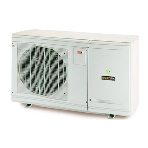
1. GENERAL 1.1 General terms of delivery Any equipment, even CARRIAGE and PACKING FREE, travel at the consignee’s risk. The consignee shall make reserves in writing on the CARRIER’S delivery bill if he notes damage caused during transport. (Confirmation to be sent to the CARRIER within 48 hours by registered mail with acknowledgement of receipt). - Page 3 2.1.1 Edenpac 2, 3, 4 and 5 Front panel with polypropylene grid. Arched ‘flat fin’ unit cooler. Motor fan unit. Anti-frost sensor. Access flap to digital regulator Fastening plates (Euro α FK) & and pressure gauge ″water flow″ (with silent blocks).
- Page 4 2.1.2 Edenpac 6 Top and bottom panels with polypropylene grid. Arched ‘flat fin’ unit cooler. Motor fan unit. Anti-frost sensor (NV). Access flap to digital regulator Fastening plates. (Euro α FK) & and pressure gauge ″water flow″ Pool inlet water connection (measures the refrigerant pressure in the HP circuit (40/49 male screw fastening) (NV).
-
Page 5: Edenpac 2, 3, 4 And
To be transported upright in its original packaging close to the installation site. Weight of Edenpac 2 with packaging : ≅ 98 kg Weight of Edenpac 3 with packaging : ≅ 101 kg Weight of Edenpac 4 - 5 with packaging : ≅ 110 kg... -
Page 6: Edenpac
2.2.2 Edenpac 6... -
Page 7: Installation
Dimensions of the appliance with packaging (in mm) : 1275 To be transported upright in its original packaging close to the installation site. Weight of Edenpac 6 with packaging: ≅ 145 kg 3. INSTALLATION Tools required for installation : 1 set of flat head screwdrivers 1 set of crosshead screwdrivers 1 cutter 1 wire stripper... - Page 8 • the installation must be simple and allow for easy maintenance interventions. • the appliance must be installed on a solid base (fastening centre distance 810 x 370) and protected against flooding (using a « concrete » base with drain facility for condensation or installation of an additional condensation evacuation kit placed at your disposal in the accessories sachet).
-
Page 9: Connections
4. CONNECTIONS 4.1 Access to the electric card 4.1.1 Edenpac with single fan Turn the clips ¼ turn clockwise on the front panel 1 using a flat head screwdriver. Unscrew the 2 screws 2 and 3 on the right side using a cross head screwdriver Slide the entire front panel forward and then down. -
Page 10: Hydraulic Connections
(see diagrams below). - Hydraulic circuit test pressure: 3 bar - Hydraulic circuit operating pressure: 1.5 bar Edenpac 2,3,4 and 5 : - Average water flow 5 to 6.5 m3/h- pressure drop 1.3 to 1.7 mCE – (0.13 to 0.17 bar) -
Page 11: Electric Connection
- Edenpac 3 : 3 x 4 mm² * (single-phase 230V/1/50Hz) - Edenpac 2 : 3 x 2.5 mm² * (single-phase 230V/1/50Hz) * This section is indicative and must be checked and adapted, if necessary, according to installation conditions . -
Page 12: Regulator Operation
• It is possible to connect a remote control module To do this use terminals : (with display) . 34-35 and 36-37 for 12 Vac supply of the interface A1 card. (signals Tx-Rx) Important : To connect the remote On/Off functions, fault and warning functions for filter start up, use cables with a section of at least 1mm². -
Page 13: Starting Up
R410A. Refrigerant gas type: • Manufacturer's gas fill value EdenPac 2 1-ph. = 850 g. - EdenPac 3 1-ph. = 1300 g. - EdenPac 4 1-ph. = 1600 g. EdenPac 5 3-ph. = 1500 g. EdenPac 6 3-ph. = 3000 g. -
Page 14: Start Up The Heat Pump
6.2 Start up the heat pump • Switch on the heat pump power supply protection device located inside the filter control cabinet. • Start filtration. • Set the by-pass and setting valves* as follows: - Valve slightly closed to increase the filter pressure from 150 to 200g (0.15 to 0.20 bar). - Valve fully open. -
Page 15: Fault And State Display
6.4 Fault and state display Info: led remains on for 120s after a fault is indicated (except in the case of a dC indication when the heat pump remains operational). Faults : Message Designation Cause Remedy Reset Alarm Cut power supply or press Sensor defective or Replace or reconnect the dSr (on) -
Page 16: Winter Storage
6.5 Winter storage • Press the button to switch the regulation to , Ofr5 is displayed for 5 s before a small red dot «stand-by» appears. • Close the valves V2 and V3 of the BY-PASS. • Open valves V4 and V5 next to the unit (if present) •... -
Page 17: Electrical Diagrams
9. ELECTRICAL DIAGRAMS 9.1 Electrical diagram of connection interface card. To J6 and J14 To J11 and J12... -
Page 18: Electrical Diagram Edenpac Single-Phase
9.2 Electrical diagram EdenPAC single-phase. IMPORTANT Elimination or shunting of one of the safety or remote control devices automatically cancels the GUARANTEE. -
Page 19: Electrical Diagram Edenpac Three-Phase
9.3 Electrical diagram EdenPAC three-phase. IMPORTANT Elimination or shunting of one of the safety or remote control devices automatically cancels the GUARANTEE. - Page 20 IMPORTANT Elimination or shunting of one of the safety or remote control devices automatically cancels the GUARANTEE. With an aim to improving its products, PSA reserves the right to modify the characteristics without prior notice – Edition 04/05-A -...
Need help?
Do you have a question about the Edenpac 2 and is the answer not in the manual?
Questions and answers