
Related Manuals for Zodiac POWER PAC 1M


Summary of Contents for Zodiac POWER PAC 1M
- Page 1 POWER PAC 1M-2M-3M Heat pump ............... Instructions for installation and use Ed. 09/2008 Réf. : 1011505-01 / 374274003-00...
- Page 2 IMPORTANT These installation instructions are an integral part of the product and must be given to the installer and kept by the user. The warnings and indications contained in the present handbook must be carefully read and understood as they provide important information relative to handling and operating safety. This handbook must therefore always be kept available for later consultation.
-
Page 3: Table Of Contents
CONTENTS ......................2 INTRODUCTION General delivery terms............................2 Packaging and content ............................2 Product name plate ............................2 Water treatment ..............................2 ........................ 3 DESCRIPTION Heat pump dimensions ...........................3 Technical characteristics..........................3 ......................4 INSTALLATION Tools required for installation ........................4 Selection of installation site..........................4 ......................5 CONNECTIONS Access to technical compartment ........................5 Hydraulics...............................5... -
Page 4: Introduction
INTRODUCTION General delivery terms All equipment, even POST and PACKAGING PAID, is shipped at the sole risk of the receiver. The latter must record all reserves in writing on the shipping note of the HAULER in the case of visible or possible transport damage (Confirmation must be sent to the HAULER by registered mail within 48 hours). -
Page 5: Description
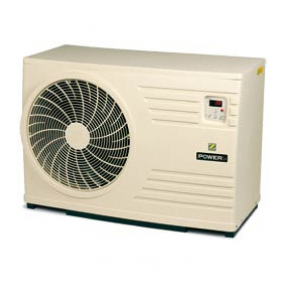
DESCRIPTION Heat pump dimensions Front panel. Fan grid. Controller. Side panel (access to technical zone). ‘Flat fin’ evaporator. Pool water inlet. Pool water outlet Cable gland. Top panel. Structural post. Base. Grooved end piece of evacuation of condensation. Product name plate. Controller On/Off or Stand-by (press and hold 3 s) -
Page 6: Installation
INSTALLATION During installation, do not pick up the unit by the top panel, use the base to lift the unit. Tools required for installation Selection of installation site • the unit must be installed outdoor. • a free space must be left around the unit (see minimum dimension in the figure below) to avoid any risk of recycling the cold air generated. -
Page 7: Connections
CONNECTIONS Access to technical compartment Hydraulics Connect the pool water inlet and outlet (respect symbols) of the unit using Ø 50 PVC pipe and the removable connectors provided with the heat pump. The following symbols will help you: for inlet and for outlet. - Page 8 • Electrical protection: by 16 A circuit-breaker (graph D) or 16 A fuse (Am) and with a 30 mA differential trip switch at the head of the supply line (circuit-breaker or switch). Earth terminal Green/Yellow Configuration of supply terminal rail. 1-phase 230V Fuse holder F1 50Hz with Phase (U) + Neutral 3.15 A Type T...
-
Page 9: Commissioning
Note: The cable used for priority heating and the electrical power supply cable must be strapped together inside the unit until just after the cable packing gland. COMMISSIONING Preliminary inspections • check that the hydraulic connections are tight. • check that the unit is stable (as well as level and upright) •... -
Page 10: Checks During Use
Remark: Once the pool has attained the required temperature, the heat pump switches off automatically (indicators off). Important remark: - If the water flow-rate through the heat pump is less than 1.2 m3/h for more than 3 seconds, the heat pump is switched to stand-by (unit off), by the flow switch and the controller displays - If the water flow-rate through the heat pump is less than 1.2 m3/h for more than 3 seconds during heat-pump operation, then it is switched off (e.g. -
Page 11: Fault Trip
Fault trip Display Designation Cause Remedy Reset Switch the power supply off and Control sensor then back on again or press the Sensor defective or Replace or reconnect the fault disconnected sensor if the message dSr is (ST1) blinking Switch the power supply off and Antifreeze sensor then back on again or press the Sensor defective or... -
Page 12: Overwintering
Display the values of sensors ST1-ST2-ST3 and ST4 (refer to the electrical diagram to identify the function of each sensor) => => -1- Press and hold for 3 s the keys display with the key (return by pressing again) => =>... -
Page 13: Electrical Wiring Diagram
ELECTRICAL WIRING DIAGRAM IMPORTANT Elimination or shunting of a safety or remote-control device automatically voids the WARRANTY. With an aim to continuous improvement, the products may be modified without prior notice. - Edition of 09/08 A - - 11 -... - Page 14 Your appliance is reaching the end of its working life. You would like to get rid of it or replace it. Please do not throw it into the dustbin or into your local council’s selective sorting containers. When this symbol appears on a new appliance, it means that the equipment must not be thrown away and that it will be collected selectively so that it can be reused, recycled or recovered.
- Page 17 ADDITIONAL RECOMMENDATIONS In relation with the Pressurised Equipment Directive (PED-97/23/CE) I. Installation and maintenance • Before beginning any installation, commissioning, operation or maintenance work, the persons responsible for these tasks must have read and understood all instructions and recommendations contained in the unit installation instructions as well as in the project technical file. •...
- Page 18 PSA - Boulevard de la Romanerie BP 90023 - 49180 Saint Barthélemy d’Anjou Cedex - France Tél. +33 2 41 21 17 30 - Fax +33 2 41 21 12 26 - www.psa-zodiac.com R.C.S. NANTERRE : 410 245 906 - Code APE : 292 F...
- Page 19 Your details may be treated according to the law Informatique et civil rights dated 6th January 1978. You got rights to access, modification and cancellation of them that should be applied to PSA- Groupe ZODIAC – Bd de la Romanerie – B.P. 90023 –...
- Page 20 été retourné dûment rempli et signé ! / CAUTION : The guaranty is valid only if this form is properly filled in , signed and sent back ! S.A.S PSA - Groupe Zodiac Boulevard de la Romanerie - B.P. 90023 – 49180 SAINT BARTHELEMY-D'ANJOU Cedex - France Avant de retourner ce coupon, n’oubliez pas d’en faire une copie !
Need help?
Do you have a question about the POWER PAC 1M and is the answer not in the manual?
Questions and answers