KB Electronics Penta Power KBRG-212D Installation And Operation Manual
Regenerative drive, variable speed scr control full wave 4-quadrant
Hide thumbs
Also See for Penta Power KBRG-212D:
Table of Contents
Advertisement
INSTALLATION AND OPERATION MANUAL
REGENERATIVE DRIVE
MODEL KBRG-212D
Part No. 8819
VARIABLE SPEED SCR CONTROL
FULL WAVE 4–QUADRANT
RoHS
See Safety
Warning, on page 5.
The information contained in this manual is intended to be accurate.
However, the manufacturer retains the right to make changes in design, which may not be included herein.
© 2009 KB Electronics, Inc.
(see back cover)
Advertisement
Table of Contents

Related Manuals for KB Electronics Penta Power KBRG-212D


Summary of Contents for KB Electronics Penta Power KBRG-212D
- Page 1 Warning, on page 5. The information contained in this manual is intended to be accurate. However, the manufacturer retains the right to make changes in design, which may not be included herein. © 2009 KB Electronics, Inc. (see back cover)
-
Page 2: Table Of Contents
TABLE OF CONTENTS Section Page Quick-Start Instructions................. 4 Safety Warning ..................5 Introduction ................... 6 Important Application Information ............12 Mounting Instructions ................12 Electrical Connections................13 Setting Selectable Jumpers / Connector..........19 Recommended High Voltage Dielectric Withstand Testing (Hi-Pot) ..23 Drive Operation .................. - Page 3 TABLE OF CONTENTS (Continued) Figure Page J8 15V / 10V Jumper ................. 22 J17 Analog Signal Input (Voltage Position)........22 J17 Analog Signal Input (Current Position) ........22 J9 Enable / Inhibit Jumper ..............22 Typical Hi-Pot Test Setup ..............24 Forward and Reverse Acceleration Trimpot Position......
-
Page 4: Quick-Start Instructions
QUICK-START INSTRUCTIONS Important: You must read these simplified instructions before proceeding. These instructions are to be used as a reference only and are not intended to replace the details provided herein. You must read the SAFETY WARNING, on page 5, before proceeding. 1.1. -
Page 5: Safety Warning
SAFETY WARNING Definition of Safety Warning Symbols Electrical Hazard Warning Symbol: Failure to observe this warning could result in electrical shock or electrocution. Operational Hazard Warning Symbol: Failure to observe this warning could result in serious injury or death. SAFETY WARNING! Please read carefully before proceeding. This product should be installed and serviced by a qualified technician, electrician, or electrical maintenance person familiar with its operation and the hazards involved. -
Page 6: Introduction
INTRODUCTION Thank you for purchasing the KBRG-212D. KB Electronics is committed to providing total customer satisfaction by producing quality products that are easy to install and operate. The KBRG-212D is manufactured with Surface Mount Technology (SMT), incorporating advanced circuitry, components and technology. -
Page 7: Standard Features
TABLE 1 – STANDARD FEATURES Feature Description Facilitates wiring of AC line, motor armature and field, Terminal Blocks TB1 (-15V, +15V, SIG, COM, EN), TB2 (L1, L2, M2, M1), TB3 (See Section 6, on page 13.) (F+, F-). Connectors J1, Tach-Generator Input – Connection point for an external (See Section 7, on page 19.) Tach-Generator. -
Page 8: Trimpot Adjustments
TABLE 3 – TRIMPOT ADJUSTMENTS (See Section 10, on pages 25) Trimpot Description Sets the amount of time for the motor to accelerate from zero speed to full speed in the Forward Acceleration (FACC). Refer to Section forward direction and the time it takes to 10.1, page 25. -
Page 9: Electrical Ratings
TABLE 4 B ELECTRICAL RATINGS Maximum AC Output Maximum Maximum Input Voltage Line Current Voltage DC Output Horsepower (VAC) (Amps RMS) (Volts DC) Current (ADC) HP, (KW) 0 – ±90 ¾, (0.5) 208/230 0 – ±180 1.5, (1) TABLE 5 B GENERAL PERFORMANCE SPECIFICATIONS Parameter Specification Factory Setting... -
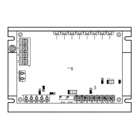
Page 10: Control Layout
FIGURE 1 B CONTROL LAYOUT... -
Page 11: Mechanical Specifications
FIGURE 2 B MECHANICAL SPECIFICATIONS (Inches / [mm]) 4.75 [120] 3.50 [88.9] 0.25 0.625 0.20 [6.35] [15.9] [5.08] 6.50 7.00 [165] [178] MAXIMUM HEIGHTS Without Accessory Boards With Accessory Boards 1.70 3.10 [43.2] [78.7]... -
Page 12: Important Application Information
IMPORTANT APPLICATION INFORMATION WARNING! DO NOT USE THIS DRIVE IN AN EXPLOSIVE ENVIRONMENT. AN EXPLOSION CAN CAUSE SERIOUS OR FATAL INJURY. THIS DRIVE IS NOT EXPLOSION PROOF. WARNING! BE SURE TO FOLLOW ALL INSTRUCTIONS CAREFULLY. FIRE OR ELECTROCUTION CAN RESULT DUE TO IMPROPER USE OF THIS PRODUCT. -
Page 13: Electrical Connections
ELECTRICAL CONNECTIONS WARNING! READ SAFETY WARNING, ON PAGE 5, BEFORE USING THIS CONTROL. CAUTION! To avoid erratic operation, do not bundle AC line and motor connections with potentiometer connections, voltage following connections, Start/Stop switch connections, inhibit connections, or any other signal connections. Use shielded cables on all signal connections over 12”... -
Page 14: Armature Fuse Chart
FIGURE 3 – AC LINE AND ARMATURE CONNECTION M2 M1 (EARTH) AC LINE ARMATURE INPUT See Table 6, for Torque Requirements. 6.3 Fusing AC Line Fuse – The KBRG-212D does not contain an AC line fuse or Armature fuse. It is recommended that a 20 Amp fuse or circuit breaker be installed on each AC line conductor not at ground potential. -
Page 15: Field Connection
TABLE 8 – FIELD CONNECTIONS (Shunt Wound Motors Only) AC LINE FIELD VOLTAGE FIELD VOLTAGE FIELD CONNECTION VOLTAGE (VDC) (VDC) F+, F- F+, L1 F+, F- F+, L1 F+, L1 *Step down operation. See Section 7.2, on page 20. 6.6 Full Voltage Field FIGURE 4 B FULL VOLTAGE FIELD CONNECTION... -
Page 16: Unidirectional Operation (Forward)
6.8 Main Speed Potentiometer Connection – The main speed potentiometer can be connected in several ways. (A 5kΩ ohm potentiometer is supplied with control. A 10K potentiometer can also be used.) See Figures 6A – 6D. 6.8.1 Unidirectional operation (FORWARD) – Connect potentiometer to terminals “+15,”... -
Page 17: Voltage Following
6.9 Signal Following – In this mode, a signal source is used to vary motor speed. 6.9.1 Voltage Following – Uses a voltage source to vary motor speed. Set J17 (See Section 7.7 on page 22 for jumper information) to “VOLT” position and connect the voltage source to TB1 terminals SIG (+) and COM (-) (See Figures 7A below and 7C, on page 18), Voltage Following Connection. -
Page 18: J17 Voltage Scale
FIGURE 7C - J17 FIGURE 7D - J8 VOLTAGE SCALE CURRENT SCALE 90V / 90V / 180 V 20mA 6.10 Enable / Inhibit – The control features an Enable / Inhibit function. The control can be electronically stopped and started with the Enable / Inhibit circuit. The Enable circuit functions opposite to that of the inhibit circuit. -
Page 19: Setting Selectable Jumpers / Connector
6.11 Tach-Generator Feedback, J1 – The KBRG-212D is FIGURE 9 – factory set for armature feedback which provides good J1 -TACH-GENERATOR load regulation for most applications. For superior FEEDBACK load regulation analog tach-generator feedback can be used. Connect the tach-generator to J1, so that the polarity of the tach-generator is the same with respect to the input signal polarity. -
Page 20: J3 Armature Voltage (90V)
7.2 J3 – Armature Voltage FIGURE 11B – J3 FIGURE 11A – J3 Output and Tach-Generator ARMATURE VOLTAGE ARMATURE VOLTAGE Feedback – Select (180V) desired armature voltage by (90V) (Default Position) placing J3 in the proper position, “A90" or “A180.” See Figure 11A. -
Page 21: Motor Speed Vs. Applied Motor Load (Torque Mode)
In the torque control mode FIGURE 14 - MOTOR SPEED vs. (J5 set to TRQ), the APPLIED MOTOR LOAD (TORQUE MODE) KBRG-212D will vary the maximum motor torque as a function of the voltage input to terminals “SIG” HIGHER TORQUE SETTING (signal) “COM”... -
Page 22: J8 15V / 10V Jumper
7.5 J8 – Analog (Signal) Input Voltage – FIGURE 16 - J8 15V / 10V The output of this control is normally controlled JUMPER with the main potentiometer. However, an analog voltage (isolated) may also be used in (Shown in the 10V Position) place of a potentiometer. -
Page 23: Recommended High Voltage Dielectric Withstand Testing (Hi-Pot)
8 RECOMMENDED HIGH VOLTAGE DIELECTRIC WITHSTAND TESTING (HI-POT TESTING) WARNING! READ SAFETY WARNING ON PAGE 5 BEFORE ATTEMPTING TO OPERATE. SEVERE INJURY OR DEATH CAN RESULT. Testing agencies such as UL, CSA, etc., usually require that equipment undergo a hi-pot test. -
Page 24: Drive Operation
FIGURE 19 - TYPICAL HI-POT TEST SETUP HIGH VOLTAGE DIELECTRIC WITHSTAND TESTER (HI-POT TESTER) LEAKAGE 0mA 10mA RETURN TEST VOLTAGE H. V. RESET ZERO MOTOR SPEED CONTROL FRAME AUX. EQUPT. 9 DRIVE OPERATION WARNING! READ SAFETY WARNING ON PAGE 5 BEFORE ATTEMPTING TO OPERATE OR SEVERE INJURY OR DEATH CAN RESULT. -
Page 25: Trimpot Adjustments
The KBRG-212D can be operated as speed controls or torque controls by setting the position of jumper J5. The Main Speed Potentiometer controls the magnitude of the mode selected. Set jumper J5 to "SPD" for speed control or to "TRQ" for torque control. See Table 10. -
Page 26: Forward And Reverse Acceleration Trimpot Position
FIGURE 20A – FORWARD AND REVERSE FIGURE 20B – ACCEL TRIMPOT ACCELERATION TRIMPOT POSITIONS ADJUSTMENT Time -100 10.2 Maximum Speed (MAX) - The MAX Trimpot is FIGURE 21 –MAXIMUM SPEED used to set the maximum output voltage of the TRIMPOT POSITION control which, in turn, sets the maximum speed of the motor. -
Page 27: Forward Current Trimpot Position
c. Apply power; Rotate CL trimpot CW until desired CL setting is reached (factory setting is 1.5 times rated motor current). Be sure control is in Forward direction for FCL trimpot adjustment and likewise with RCL. WARNING! DO NOT LEAVE MOTOR SHAFT LOCKED FOR MORE THAN 2 - 3 SECONDS, TO PREVENT MOTOR DAMAGE. -
Page 28: Response Trimpot Position
10.5 Response (RESP) - This trimpot determines the dynamic response of the control. The factory FIGURE 24 –RESPONSE setting is approximately 50% of full rotation. The TRIMPOT POSITION setting may be increased if a faster response is required. See Figure 24. Note: If response is made too fast, unstable operation may result. -
Page 29: Offset Trimpot Position
10.7 Offset (OFFSET) - This trimpot determines the amount of bias in the forward or reverse direction. The trimpot is factory set to provide approximately zero offset, which means neither the forward nor the reverse speed is favored. See Figures 26A and 26B. FIGURE 26A –... -
Page 30: Diagnostic Led's
11 DIAGNOSTIC LEDS The KBRG-212D is designed with LEDs mounted on the Control Board, to indicate the control=s operational status. See Figure 1, on page 10. 11.1 LED 1 Power On (PWR ON) -Indicates that the drive is energized with the AC line. 11.2 LED 2 Current Overload (OL) - Indicates that the drive is in Current Overload. - Page 31 Troubleshooting (Continued) Motor is overloaded. Check motor amps with DC ammeter in series with armature. (If motor is shunt type, field may be open or not receiving proper voltage.) Check motor for shorts or grounds. Motor OL LED indicator is illuminated. may be defective.
- Page 32 LIMITED WARRANTY For a period of 18 months from the date of original purchase, KB Electronics, Inc. will repair or replace without charge, devices which our examination proves to be defective in material or workmanship. This warranty is valid if the unit has not been tampered with by unauthorized persons, misused, abused, or improperly installed and has been used in accordance with the instructions and/or ratings supplied.
Need help?
Do you have a question about the Penta Power KBRG-212D and is the answer not in the manual?
Questions and answers