KB Electronics KBAC-29 Installation And Operation Manual
Kbac series.
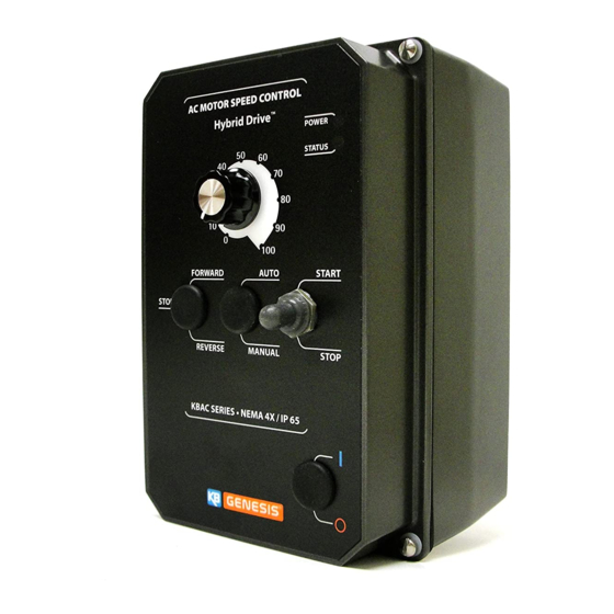
adjustable frequency drive for 3-phase ac motors
nema 4x / ip65
variable speed / soft-start ac motor drive
with electronic motor overload protection1
washdown and watertight for indoor and outdoor use
rated for 208 – 230 and 400/460 volt 50
Table of Contents
Advertisement
INSTALLATION AND OPERATION MANUAL
Adjustable Frequency Drive for 3-Phase AC Motors
3-Phase and PSC
Operates from 115, 208/230, and 400/460 Volt 50/60 Hz AC Line Input
NOTE: The drive is factory set for
60 Hz motors. For 50 Hz motors,
see Section 10.4 on page 19.
KBAC-24D, 27D, 29, 29 (1P), 45, 48, 217, 217S, 217F, 217SF, 416, 416S, 416F, 416SF
The information contained in this manual is intended to be accurate.
However, the manufacturer retains the right to make changes in design which may not be included herein.
Notes: 1. UL approved as an electronic overload protector for motors. 2. Special software is available for PSC
motors – contact Technical Support. 3. Third Generation (3G) drives are jumper selectable (J12) for standard and sensitive
GFCIs. 4. Installation of a CE approved RFI (EMI) filter is required. 5. Third Generation (3G) drives KBAC-24D, 27D, 29,
29 (1P), 45, 48 are marked "(3G)" on the product label. All KBAC-217, 416 Series drives are Third Generation (3G).
Copyright © 2017 KB Electronics, Inc.
(See Back Cover)
KBAC SERIES
NEMA 4X / IP65
Variable Speed / Soft-Start AC Motor Drive
With Electronic Motor Overload Protection
Washdown and Watertight for Indoor and Outdoor Use
Rated for 208 – 230 and 400/460 Volt 50 Hz and 60 Hz
2
AC Induction Motors from Subfractional thru 10 HP
See Safety Warnings on page 5.
This Manual Covers 2G and 3G Models
1
3
4
LISTED
IND. CONT.
EQ. – 70ZA
3,5
Scan this QR Code
to View, Download,
the Online Manual
RoHS
or Print
Advertisement
Table of Contents

Related Manuals for KB Electronics KBAC-29


Summarization of Contents
Quick Start Guide
Mounting Instructions
Instructions for mounting the drive unit.
AC Line Input Fusing
Recommendations for AC line input fusing and circuit breaker selection.
AC Line Input Connection
Guidance on connecting the AC line input to the drive.
Motor Connection
Procedure for connecting the motor to the drive's terminals.
Ground Connection
Instructions for properly grounding the drive and motor.
60 Hz and 50 Hz Motor Operation
Setting the drive for 60 Hz or 50 Hz motor operation.
Start/Stop Switch
Information on using the drive's electronic start/stop switch.
Jumper Settings Overview
Overview of factory-set jumpers and potential adjustments.
Trimpot Adjustments Overview
Guidance on adjusting trimpots for specific drive requirements.
Diagnostic LEDs
How to interpret diagnostic LEDs for drive status.
Safety Warnings
Definition of Safety Warning Symbols
Explanation of warning symbols used in the manual.
Critical Safety Instructions
Critical safety instructions for installation and servicing personnel.
Important Application Information
Motor with External Fan Cooling
Considerations for motor overheating with external fan cooling.
Electronic Motor Overload Protection
Details on the drive's I2t overload protection and current limit features.
Introduction
Standard Features
Overview of key features like die-cast enclosure, jumpers, and LEDs.
Performance Features
Description of performance characteristics like Power Start and slip compensation.
Protection Features
Details on built-in protection mechanisms such as overload and short circuit.
Mounting
KBAC-24D Mechanical Specifications
Detailed mechanical dimensions and mounting information for KBAC-24D.
Electrical Connections
AC Line Input Connection
Connecting the AC line input to the drive's terminal block.
Motor Connection
Procedure for connecting the motor to the drive's TB1 terminal block.
Ground Connection
Connecting the ground wire to the drive's ground screw.
Remote Main Speed Potentiometer Connection
Connecting a remote potentiometer to control motor speed.
Remote Start/Stop Switch Connections
Wiring remote start/stop switches to the drive.
Automatic Restart
Configuration for automatic restart after power loss.
Voltage Following Connections
Connecting an analog signal for voltage following speed control.
Enable Circuit Connection
Wiring an enable circuit to start and stop the drive.
Run/Fault Relay Connection
Connecting the Run/Fault relay output contacts.
Setting Selectable Jumpers
AC Line Input Voltage Selection (J1)
Setting Jumper J1 for 115V or 230V AC line input.
Motor Horsepower Selection (J2)
Setting Jumper J2 for motor horsepower selection.
Automatic Ride-Through or Manual Start Selection (J3)
Configuring automatic ride-through or manual start with Jumper J3.
Motor Frequency Selection (J4 and J5)
Setting Jumpers J4 and J5 for motor frequency selection.
Boost Mode Selection (J6)
Selecting fixed or adjustable boost mode using Jumper J6.
Braking Mode Selection (J7)
Choosing between regenerative braking and DC injection braking with Jumper J7.
Run/Fault Output Relay Operation Selection (J8)
Configuring Run/Fault relay operation with Jumper J8.
Stop Contact Type Selection (J9)
Selecting normally open or closed stop contact type with Jumper J9.
Torque Mode Selection (J10)
Choosing between constant and variable torque modes with Jumper J10.
Switching Frequency and GFCI Selection (J12)
Setting switching frequency and GFCI type with Jumper J12.
Drive Operation
Start-Up Procedure
Steps to follow for safely starting the drive for the first time.
Restarting After Faults
Procedure for restarting the drive after a fault condition has been resolved.
Trimpot Adjustments
Minimum Speed Trimpot (MIN)
Setting the minimum motor speed using the MIN trimpot.
Maximum Speed Trimpot (MAX)
Setting the maximum motor speed using the MAX trimpot.
Acceleration Trimpot (ACCEL)
Adjusting the acceleration time using the ACCEL trimpot.
Deceleration Trimpot (DECEL)
Adjusting the deceleration time using the DECEL trimpot.
DC Injection Brake Trimpot (DECEL)
Setting the DC injection brake time with the DECEL trimpot.
Slip Compensation Trimpot (COMP)
Adjusting slip compensation for speed regulation using the COMP trimpot.
Motor Overload (I2t) with RMS Current Limit Trimpot (CL)
Setting the current limit and overload protection with the CL trimpot.
Boost Trimpot (BOOST)
Adjusting the boost voltage for low-speed torque using the BOOST trimpot.
Jog Trimpot (JOG)
Setting the jog speed using the JOG trimpot with an optional switch.
Diagnostic LEDs
Power On LED (PWR)
Status of the Power On (PWR) LED.
Status LED (ST)
Meaning of the Status (ST) LED colors and flash rates.
Need help?
Do you have a question about the KBAC-29 and is the answer not in the manual?
Questions and answers