Table of Contents
Advertisement
Quick Links
INSTALLATION AND OPERATING INSTRUCTIONS
REGENERATIVE DRIVE
MODEL KBRG-225D
(P/N 8800)
FULL W AVE • 4 QU ADRANT
FWD
EN
REV
EN
F1
TB1
1
TB1
(EARTH)
GND
F+
See Safety Warning on Page 2
The information contained in this manual is intended to be accurate. However, the manufacturer
retains the right to make changes in design which may not be included herein.
See Page 2
A COMPLETE LINE OF MOTOR DRIVES
Spec Tech Industrial 203 Vest Ave. Valley Park, MO 63088 Phone: 888 SPECTECH
Email: sales@spectechind.com
FWD
REV
MAX
DB
ACCEL ACCEL
SPD
RESP
S/LT
NLT
J8
OFFSET
PWR
ON
T1
CL
R33
J3
2
3 4
5
6
7 8
9
10 11
12
13
AC LINE
ARMATURE
F1
FUSE
FUSE
TB2
L1
L2
M1
M2
F-
www.spectechind.com
MODEL KBRG-240D
(P/N 8802)
IR
REV
FWD
COMP
CL
CL
TCL
F2
™
© 1997 KB Electronics, Inc.
This manual
applies to
logic board
revision " L "
and newer
controls
only.
Advertisement
Table of Contents

Related Manuals for KB Electronics PENTA KB POWER KBRG-225D


Summary of Contents for KB Electronics PENTA KB POWER KBRG-225D
- Page 1 See Page 2 ™ A COMPLETE LINE OF MOTOR DRIVES © 1997 KB Electronics, Inc. Spec Tech Industrial 203 Vest Ave. Valley Park, MO 63088 Phone: 888 SPECTECH Email: sales@spectechind.com www.spectechind.com...
-
Page 2: Table Of Contents
TABLE OF CONTENTS Section Page Simplified Setup and Operating Instructions ........1 Safety Warning . -
Page 3: Simplified Setup And Operating Instructions
KBRG SIMPLIFIED OPERATING INSTRUCTIONS IMPORTANT – You must read these simplified operating instructions before you proceed. These instructions are to be used as a reference only and are not intended to replace the detailed instructions provided herein. You must read the Safety Warning on page 2 before proceeding. 1. -
Page 4: Safety Warning
ii. SAFETY WARNING! — PLEASE READ CAREFULLY This product should be installed and serviced by a qualified technician, electrician or electrical maintenance person familiar with its operation and the hazards involved. Proper installation, which includes wiring, mounting in proper enclosure, fusing or other overcurrent protection and grounding, can reduce the chance of electric shocks, fires or explosion in this product or products used with this product, such as electric motors, switches, coils, solenoids and/or relays. -
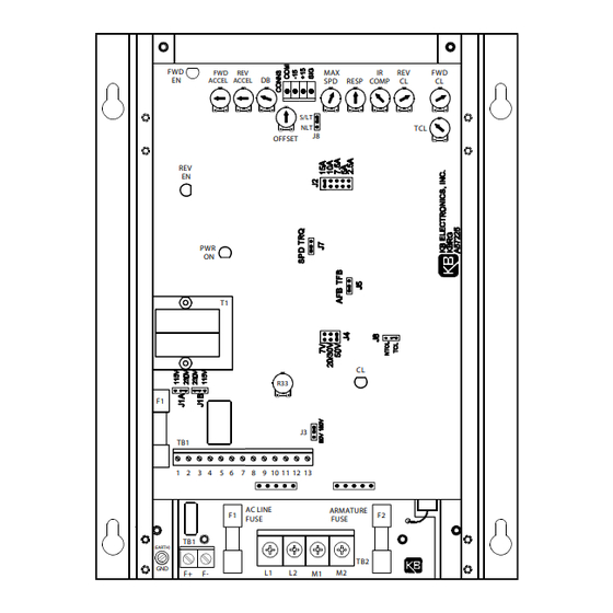
Page 5: Control Layout
FIG. 1 – CONTROL LAYOUT Illustrates Factory Setting of Jumpers and Approximate Trimpot Settings... -
Page 6: Setting Mode Of Drive (Speed Or Torque Control)
TABLE 2 – GENERAL PERFORMANCE SPECIFICATIONS Parameter Specification Factory Setting AC Line Input Voltage (VAC ±10%,50/60 Hz) 115 or 230 AC Line Frequency (Hz), # of Phases — 50/60, 1 Arm Voltage Range at 115VAC Line (VDC) 0 – ±90 —... -
Page 7: Summary Of Control Operation
TABLE 3 – SUMMARY OF CONTROL OPERATION Type of Motor Rotation Motor Torque Applied Load Quadrant Operation Direction Direction Direction Motoring Regeneration Motoring Regeneration B. Torque Control Mode – When Jumper J7 is set to “TRQ” position, the KBRG will vary motor torque. -
Page 8: Setting Selectable Jumpers
FIG. 2B – NON-LINEAR TORQUE CURVE III. SETTING SELECTABLE JUMPERS. The KBRG has customer selectable jumpers which must be set before the control can be used (refer to fig. 1 p. 3). Bold indicates Factory Setting. (See sec. II, p. 4 for J7 and J8 settings.) A. -
Page 9: Relationship Of Ac Line Input And Motor Voltage
FIG. 3 – AC LINE VOLTAGE FIG. 4 – MOTOR ARMATURE JUMPER SETTING VOLTAGE JUMPER SETTING 115VAC 230VAC 90VDC 180VDC TABLE 5 – RELATIONSHIP of AC LINE INPUT AND MOTOR VOLTAGE with J1A, J1B and J3 JUMPER POSITION J1A, J1B AC INPUT VOLTAGE J3 POSITION MOTOR VOLTAGE... -
Page 10: Mounting
Two modes of current limit are provided: 1. Timed Current Limit "TCL" – Turns the drive off after a preset time. (The time period is adjustable with the TCL trimpot from 1-15 seconds and is factory set for approximately 5 seconds.) In order for the Timed CL feature to operate, the Start/Stop circuit must be wired. -
Page 11: Mechanical Specifications
INCHES FIG. 5 – MECHANICAL SPECIFICATIONS [mm] 7.70 (195.58) 7.10 0.30 (7.62) (180.34) R0.089 (4 PL) [R2.3] 1.00 (25.40) 0.324 (4 PL) [8.2] R0.172 (4 PL) [R4.4] 10.00 (254.00) 8.00 (203.20) 10 11 AC LINE ARMATURE FUSE FUSE DWG#: C3900-1-00096 3.440 [87.4] NOTE: CONTROL SHOWN ABOVE IS MODEL KBRG-225D. -
Page 12: Field Connections
C. Field (For Shunt Wound FIG. 6 – AC LINE AND ARMATURE CONNECTION motors only) – Do not use F+ and F- terminals for any other motor type. Connect motor shunt field to terminals F+ and F- for 90VDC motors with 100VDC fields... -
Page 13: Main Speed Potentiometer Connections
FIG. 8 – MAIN SPEED POTENTIOMETER CONNECTIONS BIDIRECTIONAL BIDIRECTIONAL FORWARD REVERSE with REVERSING CONTACT with SPEED POT FIG. 9A – VOLTAGE F. Voltage Following – An isolated analog voltage can be used in FOLLOWING lieu of main speed potentiometer. Connect signal to terminals "12" and "13."... -
Page 14: Fusing
Alarm Contacts – S.P.S.T. relay contacts (terminals "3" and "4") are used to signal a warning or to shut other equipment down if control goes to an Inhibit state. Rating of contacts are 1A-28VDC, .5A-115VAC. See table 8 for relay control state vs contact state. (See fig. -
Page 15: Trimpot Adjustments
TABLE 9 – ARMATURE FUSE CHART (F2 Power Board) Motor Horsepower Approx. DC Motor Fuse Rating Current Amps (AC Amps) 90VDC 180VDC 10.0 15, 20* 15.0 * Use higher rated fuse for high ambient temperature or when rapid starting and stopping occur. Start control by applying AC power. -
Page 16: Offset Trimpot Adjustment
FIG. 11 – OFFSET TRIMPOT ADJUSTMENT B. Offset (OFFSET) – This trimpot determines the amount of bias in the forward or reverse direction. The trimpot is factory set to provide ap- proximately zero offset, which means neither the forward nor the reverse speed is favored. -
Page 17: Function Indicator Lamps
E. IR Compensation (IR Comp) – The IR Comp is used to stabilize motor speed under varying loads. (Note: If control is in Tach Feedback mode, the IR Comp should be set to minimum - CCW.) Readjust the IR Comp trimpot as follows: Run motor at approximately 30-50% of rated speed under no load and measure actual speed. -
Page 18: Limited Warranty
KB's total liability, under all circumstances, shall not exceed the full purchase price of this unit. (rev 4/88) KB ELECTRONICS, INC. 12095 NW 39th Street, Coral Springs, FL 33065 • (954) 346-4900 • Fax (954) 346-3377 Outside Florida Call TOLL FREE (800) 221-6570 • E-mail – info@kbelectronics.com www.kbelectronics.com...
Need help?
Do you have a question about the PENTA KB POWER KBRG-225D and is the answer not in the manual?
Questions and answers