Table of Contents
Advertisement
INSTALLATION AND OPERATING INSTRUCTIONS
KBWS WHISPER DRIVE
PULSE WIDTH MODULATED (PWM)
DC Motor Speed Control with Built-In
Input Signal Isolation
See Table 1 on page 10 for a list of KBWS
Models covered by this manual
The information contained
in this manual is intended to be accurate.
However, the manufacturer retains
the right to make changes in design
which may not be included herein.
Note: A PLug-In Horsepower Resistor®
must be installed for this product to
operate (supplied separately).
See Safety Warning on Page 5 before
!
installing and operating this control
A COMPLETE LINE OF MOTOR DRIVES
Hi-Pot
Tested
1500 VAC
TM
© 2001 KB Electronics, Inc.
Advertisement
Table of Contents

Related Manuals for KB Electronics KBWS-12


Summary of Contents for KB Electronics KBWS-12
- Page 1 Note: A PLug-In Horsepower Resistor® must be installed for this product to operate (supplied separately). See Safety Warning on Page 5 before Hi-Pot installing and operating this control Tested 1500 VAC A COMPLETE LINE OF MOTOR DRIVES © 2001 KB Electronics, Inc.
-
Page 2: Table Of Contents
TABLE OF CONTENTS Section Page Simplified Operating Instructions ........4 Safety Warning . - Page 3 Figures Pages 1. Control Layout ..........8 2A.
-
Page 4: Simplified Operating Instructions
SIMPLIFIED OPERATING INSTRUCTIONS IMPORTANT – You must read these simplified operating instructions before proceed- ing. These instructions are to be used as a reference only and are not intended to replace the detailed instructions provided herein. You must read the Safety Warning on page 5 before proceeding. -
Page 5: Safety Warning
SAFETY WARNING! Please read carefully This product should be installed and serviced by a qualified technician, electrician, or electrical maintenance person familiar with its operation and the hazards involved. Proper installation, which includes wiring, mounting in proper enclosure, fusing or other over current protection, and grounding can reduce the chance of electrical shocks, fires, or explosion in this product or products used with this product, such as electric motors, switches, coils, solenoids, and/or relays. -
Page 6: Introduction
INTRODUCTION Thank you for purchasing the KBWS. KB Electronics, Inc. is committed to providing total customer satisfaction by producing quality products that are easy to install and operate. The KBWS is manufactured with surface mount components incorporating advanced circuitry and technology. - Page 7 The KBWS contains built-in isolation for all signal inputs. This includes input signal voltage, Main Speed Potentiometer terminals, Inhibit Circuit and +5VDC power sup- ply. The dual voltage models contain a jumper to select motor voltage and special circuitry which automatically accepts AC Line input voltages of 115 or 208/230 Volts AC without having to make a jumper selection.
-
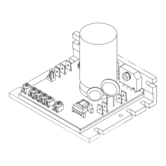
Page 8: Control Layout
FIGURE 1 – CONTROL LAYOUT (Illustrates Factory Setting of Jumpers and Approximate Trimpot Settings) 180V 90V KBWS Plug-In Horsepower Resistor® (Supplied Separately) -
Page 9: A. Mechanical Specifications
FIGURE 2A – MECHANICAL SPECIFICATIONS (Inches / [mm]) 4.30 0.48 [109.2] [12.3] 1.23 180V 90V KBWS [31.4] 2.98 [75.8] 3.62 [92.1] 3.80 [96.5]... -
Page 10: Electrical Ratings
FIGURE 2B – MECHANICAL SPECIFICATIONS (Inches / [mm]) Ø0.19 2.19 KBWS-12: [Ø4.83] [55.5] 8 PLACES 1.99 KBWS-15: [50.5] 2.19 KBWS-22D: [55.5] 1.25 3.17 0.95 [31.8] KBWS-25D: [80.5] [24.1] 3.80 96.5 TABLE 1 – ELECTRICAL RATING Maximum Horsepower Maximum Maximum AC Line Input Voltage... -
Page 11: Plug-In Horsepower Resistor
TABLE 2 – GENERAL PERFORMANCE SPECIFICATIONS Parameter Specification Factory Setting AC Line Voltage Regulation (% Base Speed) — Armature Voltage Range at 115 Volt AC Line Input (Volts DC) 0 – 130 Armature Voltage Range at 208/230 Volt AC Line Input (Volts DC) 0 –... -
Page 12: Wiring Instructions
Note: Disconnect main power when installing or changing the Plug-In Horsepower Resistor®. TABLE 3 – PLUG-IN HORSEPOWER RESISTOR® SELECTION SCR Rated Motor PWM Rated Motor Plug-In Motor CL Setting Horsepower Ranges (HP) Horsepower Ranges (HP) Horsepower Resistor® Current (Amps DC) (Amps DC) 90 Volt DC 180 Volt DC... -
Page 13: Power Connections
FIGURE 4 – POWER Warning! Do not wire switches or relays in CONNECTIONS series with the armature. Armature switching can cause catastrophic failure of motor and/or control. MOTOR A. AC Line Connection – Wire the AC line to L1 and L2 terminals, as shown in Figure 4. –... -
Page 14: Voltage Following Connection
FIGURE 6 – VOLTAGE analog signal voltage to P2 (signal) and P1 (-) ter- FOLLOWING CONNECTION minals. Adjustment of the MIN trimpot may be necessary to achieve a 0 Volt DC output with a 0 Volt DC input. 0 - 5V DC Note: The input signal can be non-isolated or earth grounded since the KBWS has built-in sig- nal isolation. -
Page 15: Setting Selectable Jumper (On Dual Voltage Models)
Potentiometer setting. When the Enable Switch is opened, the control will coast to the minimum speed setting. Warning! Do not use Enable as a safety disconnect. Use only the AC line for this purpose. FIGURE 9 – MOTOR IV. SETTING SELECTABLE JUMPER (ON DUAL VOLTAGE SELECTION VOLTAGE MODELS) All dual voltage KBWS models contain a... -
Page 16: Recommended High Voltage Dielectric Withstand Testing (Hi-Pot Testing)
RECOMMENDED HIGH VOLTAGE DIELECTRIC WITHSTAND TESTING (Hi-Pot Testing) Note: This control has been Hi-Pot tested at 1500 Volts AC. Testing agencies such as UL, CSA, VDE, etc., usually require that equipment under- go a hi-pot test. In order to prevent catastrophic damage to the speed control, which has been installed in the equipment, it is recommended that the following procedure be followed. - Page 17 FIGURE 10 – HI-POT TEST SETUP HIGH VOLTAGE DIELECTRIC WITHSTAND TESTER (HI-POT TESTER) LEAKAGE AC KILOVOLTS 10mA RETURN TEST VOLTAGE H. V. RESET CONNECT ALL SPEED CONTROL TERMINALS TOGETHER ZERO (MAIN POWER DISCONNECTED) MOTOR SPEED CONTROL AC LINE INPUT MOTOR WIRES MOTOR TERMINALS CONNECT HI-POT...
-
Page 18: Operation
Model Fuse (Amps RMS) tion. It is recommended to install a fuse (Littelfuse 326, BUSS ABC or equivalent) or a KBWS-12 circuit breaker in series with each unground- KBWS-15 ed conductor. An AC Line Fuse Kit (P/N KBWS-22D 9851) is available. - Page 19 Warning! If possible, do not adjust trimpots with main power applied. If adjustments are made with main power applied, an insu- lated adjustment tool must be used and safety glasses must be worn. High voltage exists in this control. Fire and/or electrocution can result if caution is not exercised.
- Page 20 FIGURE 13 – ACC To Calibrate the MIN Trimpot: TRIMPOT RANGE 1. Adjust the MIN trimpot to the desired position and set the Main Speed Potentiometer fully counterclockwise. 2. Monitor the armature voltage and readjust the MIN trimpot to the desired voltage. C.
- Page 21 CAUTION! Adjusting the CL above 150% of motor rating can cause overheat- ing and demagnetization of some PM motors. Consult the motor manufacturer. Do not leave the motor in a locked condition for more than a few seconds since armature damage may occur. To Calibrate the CL Trimpot: 1.
-
Page 22: Diagnostic Leds
Note: If the IR compensation is set too high, unstable (oscillatory) operation will result. To Calibrate the IR Trimpot: 1. Run the motor at approximately 30 - 50% of rated speed at no load and measure the actual speed. 2. Load the motor to the rated current. Adjust the IR trimpot so that the loaded speed is the same as the unloaded speed measured in the previous step. -
Page 23: Optional Accessories
Note: In some applications, especially those requiring the motor to cycle on and off or from one speed to another or from stop to high speed, the CL LED may blink, indicating a transient overload. This may be a normal condition for the application. 4. -
Page 24: Limited Warranty
XII. LIMITED WARRANTY For a period of 18 months from the date of original purchase, KB Electronics, Inc. will repair or replace, without charge, devices which our examination proves to be defective in material or workmanship. This warranty is valid if the unit has not been tampered with by unauthorized persons, misused, abused, or improperly installed and has been used in accordance with the instructions and/or ratings supplied.
Need help?
Do you have a question about the KBWS-12 and is the answer not in the manual?
Questions and answers