Table of Contents
Advertisement
Quick Links
INSTALLATION AND OPERATING INSTRUCTIONS
REGENERATIVE DRIVE
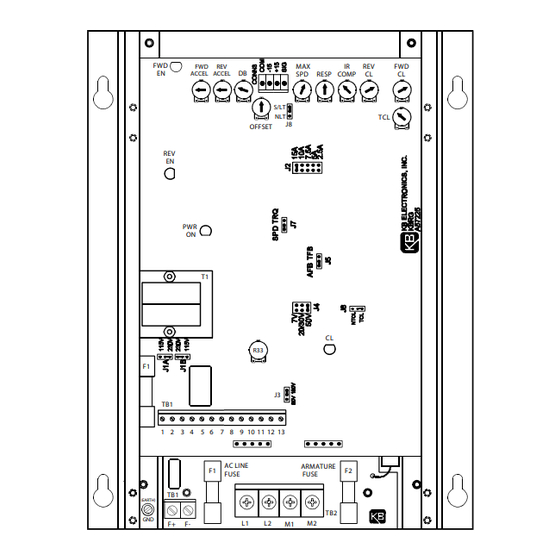
MODEL KBRG-225D
(P/N 8800)
FULL W AVE • 4 QU ADRANT
FWD
EN
REV
EN
F1
TB1
1
TB1
(EARTH)
GND
F+
See Safety Warning on Page 2
The information contained in this manual is intended to be accurate. However, the manufacturer
retains the right to make changes in design which may not be included herein.
See Page 2
A COMPLETE LINE OF MOTOR DRIVES
Spec Tech Industrial 203 Vest Ave. Valley Park, MO 63088 Phone: 888 SPECTECH
Email: sales@spectechind.com
FWD
REV
MAX
DB
ACCEL ACCEL
SPD
RESP
S/LT
NLT
J8
OFFSET
PWR
ON
T1
CL
R33
J3
2
3 4
5
6
7 8
9
10 11
12
13
AC LINE
ARMATURE
F1
FUSE
FUSE
TB2
L1
L2
M1
M2
F-
www.spectechind.com
MODEL KBRG-240D
(P/N 8802)
IR
REV
FWD
COMP
CL
CL
TCL
F2
™
© 1997 KB Electronics, Inc.
This manual
applies to
logic board
revision " L "
and newer
controls
only.
Advertisement
Table of Contents

Related Manuals for KB Electronics PENTA KB POWER KBRG-240D


Summarization of Contents
Simplified Setup and Operating Instructions
Connections
Details AC line, motor, and ground connections for the drive.
Speed or Torque Mode
Explains setting jumper J7 for speed or torque control operation.
Motor Current and Trimpot Settings
Covers jumper J2 for current selection and factory trimpot settings.
Fuses and Signal Input
Describes AC line fuse, armature fuse, and signal input connections.
Setting Mode of Drive
Speed Control Mode
Operation and requirements for speed control using J7 and J8 jumpers.
Torque Control Mode
Operation for torque control, including S/LT and NLT types.
Setting Selectable Jumpers
AC Line Voltage & Armature Voltage
Setting J1A/J1B for AC line voltage and J3 for armature voltage.
Armature Current & Feedback Options
Selecting J2 for current and J4/J5 for feedback types.
Current Limit Mode
Configuration of J6 for current limit modes (TCL/NTCL).
Mounting and Wiring
Mounting Instructions
Guidelines for physical installation and enclosure requirements.
Wiring Connections
Details AC line, motor armature, and field wiring.
Control Signals and Interfaces
Covers ground, potentiometer, enable, start/stop, and alarm contacts.
Tach-generator Input
Instructions for connecting and using a tach-generator for feedback.
Fusing
Power Board Fuses
Details AC line and armature fuse requirements and purpose.
Control Board Fuse
Information on the low-amperage fuse for the logic board.
Trimpot Adjustments
Acceleration and Deceleration
Adjusting FWD/REV ACCEL for time to reach full/zero output.
Offset and Deadband
Setting bias and rotation delay for control response.
Current Limit and Compensation
Adjusting FWD/REV CL and IR Comp for motor torque and speed stability.
Speed and Response Settings
Configuring MAX speed, response time, and TCL trimpot.
Function Indicator Lamps
Power On and Current Limit LEDs
Describes LED 1 (PWR ON) and LED 2 (CL).
Enable and Directional LEDs
Describes LED 3 (FWD EN) and LED 4 (REV EN).
Need help?
Do you have a question about the PENTA KB POWER KBRG-240D and is the answer not in the manual?
Questions and answers