Table of Contents
Advertisement
Quick Links
INSTALLATION AND OPERATING INSTRUCTIONS
REGENERATIVE DRIVE
MODEL KBRG-212D
KB Part No. 8819
VARIABLE SPEED SCR CONTROL
DESIGNED FOR SHUNT WOUND
and PM DC MOTORS
FULL WAVE • 4 QUADRANT
!
See Safety Warning on Page 2
The information contained in this manual is intended to be accurate. However, the manufacturer
retains the right to make changes in design which may not be included herein.
See Page 2
™
A COMPLETE LINE OF MOTOR DRIVES
© 1997 KB Electronics, Inc.
Advertisement
Table of Contents

Related Manuals for KB Electronics KBRG-212D


Summary of Contents for KB Electronics KBRG-212D
- Page 1 The information contained in this manual is intended to be accurate. However, the manufacturer retains the right to make changes in design which may not be included herein. See Page 2 ™ A COMPLETE LINE OF MOTOR DRIVES © 1997 KB Electronics, Inc.
-
Page 2: Table Of Contents
Page KBRG-212D Simplified Operating Instructions ....... . . 1 Safety Warning ............2 General Information . -
Page 3: Kbrg-212D Simplified Operating Instructions
KBRG-212D SIMPLIFIED OPERATING INSTRUCTIONS IMPORTANT – You must read these simplified operating instructions before you proceed. These instructions are to be used as a reference only and are not intended to replace the detailed instructions provided herein. You must read the Safety Warning on page 2 before proceeding. -
Page 4: Safety Warning
1, (1) OPERATION. The KBRG-212D will vary motor speed or torque as a function of the signal voltage on input terminals “SIG" (signal) and “COM” (common). The input voltage can be derived from the wiper of the main speed potentiometer or from an isolated analog input (voltage following mode). -
Page 5: Setting Selectable Jumpers
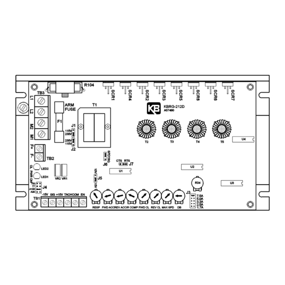
— III. SETTING SELECTABLE JUMPERS. The KBRG-212D has customer selectable jumpers which must be set before the control can be used (refer to fig. 1, p. 4). Bold indicates factory setting. See fig. 8, p. 8 for location of jumpers. -
Page 6: Jumper J3 Position Vs Motor Horsepower
B. J3 – Armature Current – Select the J3 position (1.7, 2.5, 3.3, 5, 7.5) closest to the rated motor current. (Note the maximum output current is set to 150% of the J3 position, which may be readjusted using the FWD CL and REV CL trimpots.) TABLE 4 –... -
Page 7: Jumper J5 Setting
Both forward and reverse torque are used to stabilize motor speed. (See fig. 4.) FIG. 4 – SPEED CONTROL MODE In the torque control mode (J6 set to TRQ), the KBRG-212D will vary the maximum motor torque as a function of the voltage input to terminals “SIG” (signal) and “COM” (common). -
Page 8: Mounting
Install potentiometer using hardware provided. Be sure to install insulating disk between potentiometer and inside of front panel. Enclosure – When mounting the KBRG-212D in an enclosure, it must be large enough to allow the proper heat dissipation. A 12"12"24" enclosure is suitable at full rating (7.5 Amps). -
Page 9: Field Connections (Shunt Wound Motors Only)
A. AC Line – Connect AC Line to terminals L1 and FIG. 6 – AC LINE AND L2. (Be sure jumpers J1 and J2 are set to match ARMATURE CONNECTION the AC Line voltage used.) (See table 5, p. 4.) FUSE B. -
Page 12: Main Speed Potentiometer Connections (Unidirectional)
E. Main Speed Potentiometer – The main speed potentiometer can be connected in several ways using terminals “COM,” “+15,” “SIG” and “-15.” A 5K ohm potentiometer is supplied with control. (A 10K potentiometer can also be used.) (Warning! Terminals “COM,” “+15,”... -
Page 13: Fusing
G. Enable Start/Stop Circuits – The KBRG-212D contains a 2-wire stop circuit (Enable) which is used to electronically bring the motor to a “stop.” An isolated single contact closure is required. If an isolated contact is not available, it may be necessary to use an isolation relay. -
Page 14: Vii. Trimpot Adjustments
180VDC VII. TRIMPOT ADJUSTMENTS. The KBRG-212D contains trimpots which have been factory adjusted for most applications. See specifications for factory settings. (Note: Fig. 8 p. 8 presents the various trimpots with their location. They are shown in the approximate adjustment position.) Some applications may require readjustment of trimpots in order to tailor control to exact requirements. - Page 15 B. Deadband Trimpot (DB) – The DB trimpot sets the amount of main speed potentiometer rotation required to initiate control voltage output. It is factory adjusted to approximately 25% of rotation. The DB trimpot also determines the amount of delay that will occur before regeneration starts.
-
Page 16: Viii. Function Indicator Lamps
B. Overload (OL) – Indicates the control has reached the current limit set point which has been established by the position of jumper J3 and the FWD CL and REV CL trimpot settings. In transient load applications it is normal for this light to blink. KBRG-212D ACCESSORIES • Bipolar Signal Isolator KB P/N 8801 •... -
Page 17: Ix - Limited Warranty
KB's total liability, under all circumstances, shall not exceed the full purchase price of this unit. (rev 4/88) KB ELECTRONICS, INC. 12095 NW 39th Street, Coral Springs, FL 33065 • (954) 346-4900 • Fax (954) 346-3377 Outside Florida Call TOLL FREE (800) 221-6570 • E-mail – info@kbelectronics.com www.kbelectronics.com...
Need help?
Do you have a question about the KBRG-212D and is the answer not in the manual?
Questions and answers