Table of Contents
Advertisement
INSTALLATION AND OPERATING INSTRUCTIONS
REGENERATIVE DRIVE
MODEL KBRG-255 (5HP)
KB Part No. 8821
FULL WAVE • 4 QUADRANT
FWD
FWD
MAX
IR
REV
FWD
REV
EN
ACCEL
DB
COMP
CL
ACCEL
SPD
RESP
CL
S/LT
NLT
TCL
J8
OFFSET
REV
EN
PWR
ON
CL
R33
F1
TB1
1 2 3 4 5 6 7 8 9 10 11 12 13
(EARTH)
TB1
TB2
J1
F+ F-
GND
L1
L2
M2
M1
See Safety Warning on Page 1
The information contained in this manual is intended to be accurate. However, the manufacturer
retains the right to make changes in design which may not be included herein.
™
A COMPLETE LINE OF MOTOR DRIVES
© 1999 KB Electronics, Inc.
Advertisement
Table of Contents

Related Manuals for KB Electronics Penta Power KBRG-255


Summary of Contents for KB Electronics Penta Power KBRG-255
- Page 1 The information contained in this manual is intended to be accurate. However, the manufacturer retains the right to make changes in design which may not be included herein. ™ A COMPLETE LINE OF MOTOR DRIVES © 1999 KB Electronics, Inc.
- Page 2 SUPPLEMENTAL INFORMATION These Controls have been Converted to Surface Mount Technology (SMT) The OFFSET and TCL trimpots have been moved to be aligned with the other trimpots. The General Performance Specifications, Electrical Ratings, Mechanical Specifications, and Connection Diagrams have not changed. See the figure below for the Trimpot and Jumper location changes.
-
Page 3: Table Of Contents
TABLE OF CONTENTS Section Page Simplified Setup and Operating Instructions ........1 Safety Warning . -
Page 4: Simplified Setup And Operating Instructions
KBRG-255 SIMPLIFIED OPERATING INSTRUCTIONS IMPORTANT – You must read these simplified operating instructions before you proceed. These instructions are to be used as a reference only and are not intended to replace the detailed instructions provided herein. You must read the Safety Warning before proceeding. 1. -
Page 5: General Information
This product complies with all CE directives pertinent at the time of manufacture. Contact factory for detailed installation instructions and Declaration of Conformity. Installation of a CE approved RFI filter is required. Additional shielded motor cable and/or AC line cables may be required along with a signal isolator (SI-4X, KB P/N 8801 or equivalent). -
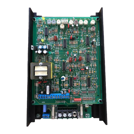
Page 6: Control Layout
FIG. 1 – CONTROL LAYOUT Illustrates Factory Setting of Jumpers and Approximate Trimpot Settings ACCEL COMP ACCEL RESP S/LT OFFSET 1 2 3 4 5 6 7 8 9 10 11 12 13 (EARTH) F+ F- DWG#:C3900-2-00992... -
Page 7: Setting Mode Of Drive (Speed Or Torque Control)
SETTING MODE OF DRIVE (SPEED OR TORQUE CONTROL). The KBRG-255 can be operated as a speed control or torque control by setting the position of jumper J7. The main speed potentiometer controls the magnitude of the mode selected. Set jumper J7 to "SPD" for speed control or to "TRQ" for torque control. (See fig. 1, p. 3.) A. -
Page 8: Setting Selectable Jumpers
FIG. 2A – LINEAR TORQUE CURVE FIG. 2B – NON-LINEAR TORQUE CURVE III. SETTING SELECTABLE JUMPERS. The KBRG-255 has customer selectable jumpers which must be set before the control can be used (refer to fig. 1 p. 3). Bold indicates Factory Setting. (See sec. II, p. 4 for J7 and J8 settings.) A. -
Page 9: Mounting
For example, if the tach is 25V/KRPM and the motor speed is 3,600 RPM, use the "50V" J4 position. For other tach-generator voltages and motor speeds, an external resistor (RT) may be used as follows. Install resistor in series with either tach-generator lead. Place J4 in "7V"... -
Page 10: Terminal Block Wiring Information
TABLE 4 – TERMINAL BLOCK WIRING INFORMATION Supply Wire Gauge* Maximum Terminal Block Connection Tightening Maximu Designation Designation Minimum Torque (lb inch) TB1 (Power Board) F+, F- TB1 (Logic Board) Logic Connections L1, L2, M1, M2 *AWG, Cu wire only. A. -
Page 11: Mechanical Specifications
INCHES FIG. 5 – MECHANICAL SPECIFICATIONS [mm]... -
Page 12: Main Speed Potentiometer Connections
Bidirectional operation using reversing contacts – Connect to terminals "10," "11," "12," "13" as per fig. 6. iii. Bidirectional operation with potentiometer – Connect potentiometer to terminals "10," "11," "12" as per fig. 6. FIG. 6 – MAIN SPEED POTENTIOMETER CONNECTIONS BIDIRECTIONAL BIDIRECTIONAL FORWARD... -
Page 13: Fusing
FIG. 7D – ALARM CONTACTS FIG. 7B – ENABLE FIG. 7C – START/STOP CIRCUIT ALARM CONTACTS TABLE 6 – CONTROL STATE vs RELAY CONTACT STATE Relay Contact State Description of Control State Using Start / Stop Start / Stop Bypassed No power to control Power applied Control in Stop mode... -
Page 14: Viii. Trimpot Adjustments
VIII. TRIMPOT ADJUSTMENTS. The KBRG-255 contains many trimpots which have been factory adjusted for most applications. (See table 2, p. 2. for factory settings.) (Note: fig. 1, p. 3 presents the various trimpots with their locations. They are shown in the approximate adjustment position.) Some applications may require readjustment of trimpots in order to tailor control to exact requirements. - Page 15 C. Deadband (DB) – The DB trimpot sets the amount of main speed potentiometer rotation required to initiate control voltage output. It is factory adjusted to approximately 25% of rotation. The DB trimpot also determines the amount of delay that will occur before regeneration starts.
-
Page 16: Function Indicator Lamps
G. Response (RESP) Trimpot – This trimpot determines the dynamic response of the control. The factory setting is approximately 50% of full rotation. The setting may be increased if a faster response is required. (Note: If response is made too fast, unstable operation may result.) H. -
Page 20: Limited Warranty
KB's total liability, under all circumstances, shall not exceed the full purchase price of this unit. (rev 4/88) KB ELECTRONICS, INC. 12095 NW 39th Street, Coral Springs, FL 33065 • (954) 346-4900 • Fax (954) 346-3377 Outside Florida Call TOLL FREE (800) 221-6570 • E-mail – info@kbelectronics.com www.kbelectronics.com...
Need help?
Do you have a question about the Penta Power KBRG-255 and is the answer not in the manual?
Questions and answers