Table of Contents
Advertisement
Advertisement
Table of Contents
Troubleshooting

Subscribe to Our Youtube Channel
Related Manuals for Keysight Technologies 85032B


Summary of Contents for Keysight Technologies 85032B
- Page 1 Keysight 85032B/E 50 Type-N Calibration Kits User’s and Service Guide...
- Page 3 User’s and Service Guide Keysight Technologies 85032B/E 50 Type-N Calibration Kits Agilent Part Number: 85032-90020 Printed in USA Print Date: August 2010 Supersedes: March 2010 © Copyright 1993, 2000, 2002, 2007, 2009, 2010 Keysight Technologies. All rights reserved.
- Page 4 CONTROL. Assistance Product maintenance agreements and other customer assistance agreements are available for Keysight products. For any assistance, contact Keysight Technologies. Refer to Contacting Keysight on page 5-4. Printing Copies of Documentation from the Web To print copies of documentation from the Web, download the PDF file from the Keysight web site: •...
-
Page 5: Table Of Contents
Final Connection Using a Torque Wrench..........3-12 Connecting and Disconnecting the Two-Piece Female Open (85032B) ......3-14 How to Separate a Connection . - Page 6 A Standard Definitions Class Assignments and Standard Definitions Values are Available on the Web ......A-2 Contents-iv 85032B/E...
-
Page 7: General Information
General Information 85032B/E 1- 1... -
Page 8: Calibration Kit Overview
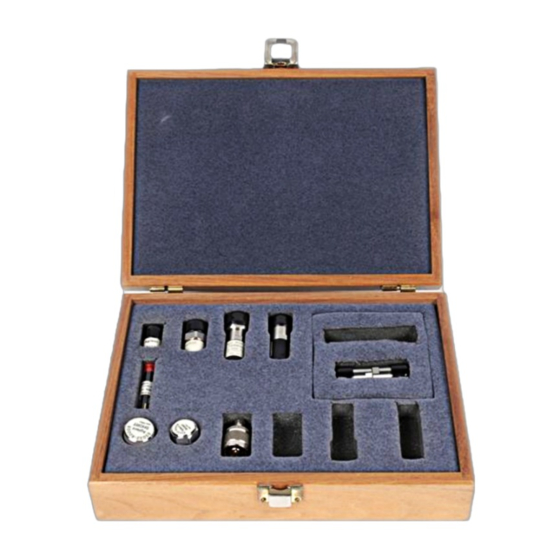
General Information Calibration Kit Overview Calibration Kit Overview The Keysight 85032B and 85032E type-N calibration kits are used to calibrate Keysight network analyzers up to 6 GHz for measurements of components with 50type-N connectors. Kit Contents Use the Contents List in the shipping container to verify the completeness of your shipment. Although this list is the most accurate, you can also use the illustrations in Chapter 7 to verify the items in your shipment. -
Page 9: Installation Of The Calibration Definitions
If the calibration definitions for the kit are not permanently installed in the network analyzer, they must be manually entered. Refer to your network analyzer user’s guide for instructions. Options The following options are available for the Keysight 85032B/E. Option 100 (85032B only) Option 100 adds the four type-N to 7-mm adapters to the calibration kit. -
Page 10: Equipment Required But Not Supplied
• the name of a technical contact person within your company, and the person's complete phone number • the model number and serial number of the kit • the part number and serial number of the device • the type of service required • a detailed description of the problem 1- 4 85032B/E... -
Page 11: Recording The Device Serial Numbers
Table 1-1 for the 85032B and Table for the 85032E. Recording the serial numbers will prevent confusing the devices in this kit with similar devices in other kits. Table 1-1 Serial Number Record for 85032B Device Serial Number Calibration kit _______________________________... -
Page 12: Clarifying The Terminology Of A Connector Interface
Improper connections, resulting from pin depth values being out of the observed limits (see Table 2-2 on page 2-4), or from bad connections, can also damage these devices. 1- 6 85032B/E... -
Page 13: When To Calibrate
Periodically remeasure the device and note any changes in its corrected response which can be attributed to the test system. With experience you will be able to see changes in the reference responses that indicate a need to perform the measurement calibration again. 85032B/E... - Page 14 General Information When to Calibrate 1- 8 85032B/E...
-
Page 15: Specifications
Specifications 85032B/E 2- 1... -
Page 16: Environmental Requirements
During a measurement calibration, the temperature of the calibration devices must be stable and within the range specified in Table 2-1. IMPORTANT Avoid unnecessary handling of the devices during calibration because your fingers are a heat source. 2- 2 85032B/E... -
Page 17: Mechanical Characteristics
They are, however, important supplemental characteristics related to electrical performance. Keysight Technologies verifies the mechanical characteristics of the devices in this kit with special gaging processes and electrical testing. This ensures that the device connectors do not exhibit any improper pin depth when the kit leaves the factory. - Page 18 Approximately +2 sigma to 2 sigma of gage uncertainty based on studies done at the factory according to recommended procedures. b. Observed pin depth limits are the range of observation limits seen on the gage reading due to measurement uncertainty. The depth could still be within specifications. 2- 4 85032B/E...
-
Page 19: Electrical Specifications
. Certification Keysight Technologies certifies that this product met its published specifications at the time of shipment from the factory. Keysight further certifies that its calibration measurements are traceable to the United States National Institute of Standards and Technology (NIST) to the extent allowed by the Institute's calibration facility, and to the calibration facilities of other International Standards Organization members. - Page 20 Specifications Electrical Specifications 2- 6 85032B/E...
-
Page 21: Use, Maintenance, And Care Of The Devices
Use, Maintenance, and Care of the Devices 85032B/E 3- 1... -
Page 22: Electrostatic Discharge
3. Connect the other end of the cable to the test port. 4. Remove the short from the cable. Refer to Chapter 6, Replaceable Parts for part numbers and instructions for ordering ESD protection devices. Figure 3-1 ESD Protection Setup 3- 2 85032B/E... -
Page 23: Visual Inspection
If a connector shows deep scratches or dents, particles clinging to the mating plane surfaces, or uneven wear, clean and inspect it again. Devices with damaged connectors should be discarded. Determine the cause of damage before connecting a new, undamaged connector in the same configuration. 85032B/E... -
Page 24: Inspect Female Connectors
Clean the connector threads. c. Let the alcohol evaporate, then blow the threads dry with a gentle stream of clean, low-pressure compressed air or nitrogen. Always completely dry a connector before you reassemble or use it. 3- 4 85032B/E... - Page 25 Let the alcohol evaporate, then blow the connector dry with a gentle stream of clean, low-pressure compressed air or nitrogen. Always completely dry a connector before you reassemble or use it. 4. Reinspect Inspect the connector again to make sure that no particles or residue are present. 85032B/E...
-
Page 26: Gaging Connectors
Use, Maintenance, and Care of the Devices Gaging Connectors Gaging Connectors The gages available from Keysight Technologies are intended for preventive maintenance and troubleshooting purposes only. (See Table 6-3 on page 6-5 for part number information.) They are effective in detecting excessive center conductor protrusion or recession, and conductor damage on DUTs, test accessories, and the calibration kit devices.Do not use the gages for precise pin depth measurements. -
Page 27: When To Gage Connectors
If the center conductor protrudes, the indicator will move clockwise to indicate the amount of protrusion, which is read as a positive value. Refer to Depth on page 2-3 for definitions of protrusion and recession. Figure 3-2 Reading the Connector Gage 85032B/E... -
Page 28: Gaging Procedures
After each measurement, rotate the gage a quarter-turn to reduce measurement variations that result from the gage or the connector face not being exactly perpendicular to the center axis. e. Compare the average reading with the observed pin depth limits in Table 2-2 on page 2-4. 3- 8 85032B/E... - Page 29 Use, Maintenance, and Care of the Devices Gaging Connectors Figure 3-3 Gaging Male Type-N Connectors 85032B/E...
-
Page 30: Gaging Female Type-N Connectors
After each measurement, rotate the gage a quarter-turn to reduce measurement variations that result from the gage or the connector face not being exactly perpendicular to the center axis. e. Compare the average reading with the observed pin depth limits in Table 2-2 on page 2-4. 3- 10 85032B/E... - Page 31 Use, Maintenance, and Care of the Devices Gaging Connectors Figure 3-4 Gaging Female Type-N Connectors 85032B/E 3-11...
-
Page 32: Connections
Table 3-1 Torque Wrench Information Connector Type Torque Setting Torque Tolerance Type-N 135 N-cm (12 in-lb) 13.5 N-cm (1.2 in-lb) Using a torque wrench guarantees that the connection is not too tight, preventing possible connector 3- 12 85032B/E... - Page 33 4. Hold the torque wrench lightly, at the end of the handle only (beyond the groove). See Figure 3-6. Figure 3-6 Using the Torque Wrench 5. Apply downward force perpendicular to the wrench handle. See Figure 3-6. This applies torque to the connection through the wrench. 85032B/E 3-13...
-
Page 34: Connecting And Disconnecting The Two-Piece Female Open (85032B)
Connecting and Disconnecting the Two-Piece Female Open (85032B) The female open standard in the 85032B calibration kit is composed of two parts: the open body (outer conductor) and the center conductor extender. Refer to Figure 3-7. -
Page 35: Handling And Storage
• Do not set connectors contact-end down on a hard surface. The plating and the mating plane surfaces can be damaged if the interface comes in contact with any hard surface. 85032B/E 3-15... - Page 36 Use, Maintenance, and Care of the Devices Handling and Storage 3- 16 85032B/E...
-
Page 37: Performance Verification
Performance Verification 85032B/E 4- 1... -
Page 38: Introduction
Introduction Introduction The performance of your calibration kit can only be verified by returning the kit to Keysight Technologies for recertification. The equipment required to verify the specifications of the devices in the kit has been specially manufactured and is not commercially available. -
Page 39: Recertification
A list of NIST traceable numbers may be purchased upon request to be included in the calibration report. Keysight Technologies offers a Standard calibration for the recertification of this kit. For more information, contact Keysight Technologies. See Contacting Keysight on page 5-4. - Page 40 Performance Verification Recertification 4- 4 85032B/E...
-
Page 41: Troubleshooting
Troubleshooting 85032B/E 5- 1... -
Page 42: Troubleshooting Process
Troubleshooting Troubleshooting Process Troubleshooting Process If you suspect a bad calibration, or if your network analyzer does not pass performance verification, follow the steps in Figure 5-1. Figure 5-1 Troubleshooting Flowchart 5- 2 85032B/E... -
Page 43: Where To Look For More Information
5-4. Returning a Kit or Device to Keysight If your kit or device requires service, contact Keysight Technologies for information on where to send it See Contacting Keysight on page 5-4 for contact information. Include a service tag (located near the end of this manual) on which you provide the following information: •... -
Page 44: Contacting Keysight
NOTE In any correspondence or telephone conversation, refer to the Keysight product by its model number and full serial number. With this information, the Keysight representative can determine whether your product is still within its warranty period. 5- 4 85032B/E... -
Page 45: Replaceable Parts
Replaceable Parts 85032B/E 6- 1... -
Page 46: Introduction
Replaceable Parts Introduction Introduction Table 6-1 lists the replacement part numbers for items in the 85032B calibration kit. Table 6-2 lists the replacement part numbers for items included in the 85032E calibration kit and Contacting Keysight on page 5-4 illustrates each of these items. - Page 47 Replaceable Parts Introduction Figure 6-1 Replaceable Parts for the 85032B Calibration Kit 85032B/E...
- Page 48 Male end cap for type-N and 7 mm as required 1401-0214 Miscellaneous Items 85032-90020 User’s and service guide a. Refer to Printing Copies of Documentation from the Web on page -4 Figure 6-2 Replaceable Parts for the 85032E Calibration Kit 6- 4 85032B/E...
- Page 49 Anhydrous isopropyl alcohol (92% pure) Cleaning swabs 9301-1243 Clarifying the Terminology of a Connector a. To ensure you choose the correct gage, refer to, Interface on page 1-6 b. Keysight can no longer safely ship isopropyl alcohol, so customers should purchase it locally. 85032B/E...
- Page 50 Replaceable Parts Introduction 6- 6 85032B/E...
-
Page 51: A Standard Definitions
Standard Definitions 85032B/E A- 1... -
Page 52: Class Assignments And Standard Definitions Values Are Available On The Web
It also provides some examples of how to set up a new calibration kit and how to modify an existing calibration kit definition file. To download a free copy, go to www.keysight.com and enter literature number 5989-4840EN in the Search window. A- 2 85032B/E... - Page 53 Keysight Technologies characteristics supplies contents mechanical part numbers supplemental when making connections 3-12 class assignments downloading from Keysight Web site damage female open...
- Page 54 Keysight Technologies performance verification downloading from Keysight Web site application note fail contacting permanently stored calibration standards definitions calibration contents...
- Page 55 3-14 verification performance temperature visual inspection warranty, documentation when to calibrate wrench open-end 3-14 part number undoing connections 3-14 torque part number wrenches part numbers zeroing connector gage 3-10 zeroing connector gage 3-10 85032B/E Index...
- Page 56 Index 85032B/E Index-4...
- Page 57 This information is subject to change without notice. © Keysight Technologies 1993 - 2014 August 2014 *85032-90020* 85032-90020 www.keysight.com...
Need help?
Do you have a question about the 85032B and is the answer not in the manual?
Questions and answers