Table of Contents
Advertisement
Quick Links
Advertisement
Table of Contents
Troubleshooting

Related Manuals for Keysight Technologies 85052B


Summary of Contents for Keysight Technologies 85052B
- Page 1 Keysight Technologies 85052B 3.5 mm Calibration Kit User’s and Service Guide...
- Page 3 85052B...
- Page 4 FAR 52.227-19 (June 1987) or any equivalent agency regulation or contract clause. Use, duplication or disclosure of Software is subject to Keysight Technologies’ standard commercial license terms, and non-DOD Departments and Agencies of the U.S. Government will receive no greater than Restricted Rights as defined in FAR 52.227-19(c)(1-2) (June 1987).
-
Page 5: Table Of Contents
Using the Sliding Load ................3-18 85052B... - Page 6 A Standard Definitions Class Assignments and Standard Definitions Values are Available on the Web......A-2 85052B...
-
Page 7: General Information
General Information... -
Page 8: Calibration Kit Overview
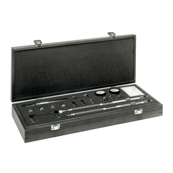
General Information Calibration Kit Overview Calibration Kit Overview The Keysight 85052B 3.5 mm calibration kit is used to calibrate Keysight network analyzers up to 26.5 GHz for measurements of components with 3.5-mm connectors. Kit Contents The 85052B calibration kit includes the following items: •... -
Page 9: Adapters
Equipment Required but Not Supplied Connector cleaning supplies and various electrostatic discharge (ESD) protection devices are not supplied with the calibration kit but are required to ensure successful operation of the kit. Refer to Table 6-2 on page for ordering information. 85052B... -
Page 10: Incoming Inspection
“Contacting Keysight” on page 5-5. Keysight will arrange for repair or replacement of incomplete or damaged shipments without waiting for a settlement from the transportation company. See “Returning a Kit or Device to Keysight” on page 5-4. 1- 4 85052B... -
Page 11: Recording The Device Serial Numbers
1-1. Recording the serial numbers will prevent confusing the devices in this kit with similar devices from other kits. The adapters included in the kit are for measurement convenience only and are not serialized. Table 1-1 Serial Number Record for the 85052B Device Serial Number... -
Page 12: Precision Slotless Connectors
With PSCs on test ports and standards, the percentage of accuracy achieved when measuring at 50 dB return loss levels is comparable to using conventional slotted connectors measuring devices having only 30 dB return loss. This represents an accuracy improvement of about 10 times. 1- 6 85052B... -
Page 13: Clarifying The Terminology Of A Connector Interface
Improper connections, resulting from pin depth values being out of the observed limits (see Table 2-2 on page 2-4) or from bad connection techniques, can also damage these devices. 85052B... -
Page 14: When To Calibrate
Periodically remeasure the device and note any changes in its corrected response which can be attributed to the test system. With experience you will be able to see changes in the reference responses that indicate a need to perform the measurement calibration again. 1- 8 85052B... -
Page 15: Specifications
Specifications... -
Page 16: Environmental Requirements
During a measurement calibration, the temperature of the calibration devices must be stable and within the range shown in Table 2-1. IMPORTANT Avoid unnecessary handling of the devices during calibration because your fingers are a heat source. 2- 2 85052B... -
Page 17: Mechanical Characteristics
They are, however, important supplemental characteristics related to electrical performance. Keysight Technologies verifies the mechanical characteristics of the devices in the kit with special gaging processes and electrical testing. This ensures that the device connectors do not exhibit any center conductor protrusion or improper pin depth when the kit leaves the factory. - Page 18 Approximately +2 sigma to 2 sigma of gage uncertainty based on studies done at the factory according to recommended procedures. b. Observed pin depth limits are the range of observation limits seen on the gage reading due to measurement uncertainty. The depth could still be within specifications. 2- 4 85052B...
-
Page 19: Electrical Specifications
Electrical Specifications The electrical specifications in Table 2-3 apply to the devices in your calibration kit when connected with a Keysight precision interface. Table 2-3 Electrical Specifications for 85052B 3.5 mm Devices Device Specification Frequency (GHz) Broadband loads Return loss 46dB 0.00501) dc to ... -
Page 20: Residual Errors After Calibration
Verification” section of the 8510C On-Site Service Manual for information on how to use the software. Certification Keysight Technologies certifies that this product met its published specifications at the time of shipment from the factory. Keysight further certifies that its calibration measurements are traceable to the United States National Institute of Standards and Technology (NIST) to the extent allowed by the Institute's calibration facility, and to the calibration facilities of other International Standards Organization members. - Page 21 Use, Maintenance, and Care of the Devices...
-
Page 22: Use, Maintenance, And Care Of The Devices Electrostatic Discharge
4. Remove the short from the cable. Figure 3-1 shows a typical ESD protection setup using a grounded mat and wrist strap. Refer to Chapter 6 for information on ordering supplies for ESD protection. Figure 3-1 ESD Protection Setup 3- 2 85052B... -
Page 23: Visual Inspection
Inspect the contact fingers in the female center conductor carefully. These can be bent or broken, and damage to them is not always easy to see. A connector with damaged contact fingers will not make good electrical contact and must be replaced. 85052B... -
Page 24: Cleaning Connectors
(60 psi) to control the velocity of the air stream. High-velocity streams of compressed air can cause electrostatic effects when directed into a connector. These electrostatic effects can damage the device. Refer to “Electrostatic Discharge” earlier in this chapter for additional information. 2. Clean the Connector Threads 3- 4 85052B... - Page 25 Let the alcohol evaporate, then blow the connector dry with a gentle stream of clean, low-pressure compressed air or nitrogen. Always completely dry a connector before you reassemble or use it. 4. Inspect Inspect the connector to make sure that no particles or residue remain. Refer to “Visual Inspection” on page 3-3. 85052B...
-
Page 26: Gaging Connectors
Gaging Connectors Gaging Connectors The gages available from Keysight Technologies are intended for preventive maintenance and troubleshooting purposes only. They are effective in detecting excessive center conductor protrusion or recession, and conductor damage on DUTs, test accessories, and the calibration kit devices.Do not use the gages for precise pin depth measurements. -
Page 27: When To Gage Connectors
(due to wear or damage, for example). • If a calibration device is used by someone else or on another system or piece of equipment. • Initially, after every 100 connections, and after that, as often as experience indicates. 85052B... -
Page 28: Gaging Procedures
After each measurement, rotate the gage a quarter-turn to reduce measurement variations that result from the gage or the connector face not being exactly perpendicular to the center axis. e. Compare the average reading with the observed pin depth limits in Table 2-2 on page 2-4. 3- 8 85052B... - Page 29 Use, Maintenance, and Care of the Devices Gaging Connectors Figure 3-2 Gaging 3.5 mm Connectors 85052B...
-
Page 30: Gaging The 3.5 Mm Sliding Loads
Pull the sliding ring back approximately 0.5 in and install a centering bead (if not already installed) in the connector end of the sliding load. CAUTION The sliding load center conductor can be damaged if the sliding load is not in alignment with the mating connector while making the connection. 3- 10 85052B... - Page 31 Compare the average reading with the observed pin depth limits in Table 2-2 on page 2-4. If the pin depth is outside the limits, it must be adjusted before proceeding. Refer to “Adjusting the Sliding Load Pin Depth” on page 3-12. 85052B 3-11...
-
Page 32: Adjusting The Sliding Load Pin Depth
Return the center conductor pullback mechanism to the rear of the sliding load and return the pullback handle to its locked position. Adjusting the Sliding Load Pin Depth The sliding loads in this kit have a setback mechanism that allows the pin depth to be set to any desired 3- 12 85052B... - Page 33 The gage reading should return to the value previously set. If not, repeat steps 4 through 7. 8. Return to “Gaging the 3.5 mm Sliding Loads” on page 3-10. Figure 3-4 Adjusting the Sliding Load Pin Depth 85052B 3-13...
-
Page 34: Connections
Table 3-1 Torque Wrench Information Connector Type Torque Setting Torque Tolerance 3.5 mm 90 N-cm (8 in-lb) 9.0 N-cm (0.8 in-lb) Using a torque wrench guarantees that the connection is not too tight, preventing possible connector 3- 14 85052B... - Page 35 4. Tighten the connection just to the torque wrench break point. The wrench handle gives way at its internal pivot point. See Figure 3-6 on page 3-15. Do not tighten the connection further. 85052B 3-15...
-
Page 36: Connecting The Sliding Load
Always move the center conductor pullback mechanism back before locking the handle. Do not force the handle past the locked position. 7. Move the center conductor pullback mechanism back (away from the connector end of the sliding load), and place the pullback handle in its locked position. 3- 16 85052B... -
Page 37: How To Separate A Connection
1. Use an open-end wrench to prevent the device body from turning. 2. Use another open-end wrench to loosen the connecting nut. 3. Complete the separation by hand, turning only the connecting nut. 4. Pull the connectors straight apart without twisting, rocking, or bending either of the connectors. 85052B 3-17... -
Page 38: Using The Sliding Load
2. Enter your VNA model number (Ex: N5242A) in the Search box and click Search. 3. Under the heading Manuals & Guides, click on the title/hyperlink for the document PDF you want to view. “Where to Look for More Information” on page 5-3. If you need additional information, see 3- 18 85052B... -
Page 39: Handling And Storage
• Do not set connectors contact-end down on a hard surface. The plating and the mating plane surfaces can be damaged if the interface comes in contact with any hard surface. 85052B 3-19... - Page 40 Use, Maintenance, and Care of the Devices Handling and Storage 3- 20 85052B...
-
Page 41: Performance Verification
Performance Verification... -
Page 42: Introduction
Introduction Introduction The performance of your calibration kit can only be verified by returning the kit to Keysight Technologies for recertification. The equipment required to verify the specifications of the devices in the kit has been specially manufactured and is not commercially available. -
Page 43: Recertification
A list of NIST traceable numbers may be purchased upon request to be included in the calibration report. Keysight Technologies offers a Standard calibration for the recertification of the kit. For more information, contact Keysight Technologies. Refer to “Contacting Keysight” on page 5-5 for a list of offices. - Page 44 Performance Verification Recertification 4- 4 85052B...
-
Page 45: Troubleshooting
Troubleshooting... -
Page 46: Troubleshooting Process
Troubleshooting Troubleshooting Process Troubleshooting Process If you suspect a bad calibration, or if your network analyzer does not pass performance verification, follow the steps in Figure 5-1. Figure 5-1 Troubleshooting Flowchart 5- 2 85052B... -
Page 47: Where To Look For More Information
2. Enter your analyzer model number (Ex: N5242A) in the Search box and click Search. 3. Under the heading Manuals, click on the title/hyperlink for the document PDF you want to view. “Contacting Keysight” on page 5-5. If you need additional information, see 85052B... -
Page 48: Returning A Kit Or Device To Keysight
Returning a Kit or Device to Keysight Returning a Kit or Device to Keysight If your kit or device requires service, contact Keysight Technologies for information on where to send it. See “Contacting Keysight” on page 5-5 for contact information. Include a service tag (located near the end of this manual) on which you provide the following information: •... -
Page 49: Contacting Keysight
If you do not have access to the Internet, please contact your Keysight field engineer. NOTE In any correspondence or telephone conversation, refer to the Keysight product by its model number and full serial number. With this information, the Keysight representative can determine whether your product is still within its warranty period. 85052B... - Page 50 Troubleshooting Contacting Keysight 5- 6 85052B...
-
Page 51: Replaceable Parts
Replaceable Parts... -
Page 52: Introduction
Replaceable Parts Introduction Introduction Table 6-1 lists the replacement part numbers for the 85052B calibration kit. Table 6-2 lists the replacement part numbers for items not included in the calibration kit that are either required or recommended for successful operation of the kit. - Page 53 Replaceable Parts Introduction Table 6-1 Replaceable Parts for the 85052B Calibration Kit Qty Per Keysight Part Number Description Box (without foam pads) 5180-7900 Foam pad (for lid) 5181-5543 Foam pad (for lower case) 85052-80031 Connector Gages (3.5 mm) Gage Set (for female connectors)
- Page 54 Keysight can no longer safely ship isopropyl alcohol, so customers should purchase it locally. “Inspect Female b. All female connectors on the precision devices in this kit are slotless connectors. Refer to Connectors” on page 3-3 6- 4 85052B...
- Page 55 Replaceable Parts Introduction Figure 6-1. Replaceable Parts for the 85052B Calibration Kit 85052B...
- Page 56 Replaceable Parts Introduction Figure 6-2 Replaceable Parts for the 85052B Calibration Kit 6- 6 85052B...
-
Page 57: A Standard Definitions
Standard Definitions... -
Page 58: Class Assignments And Standard Definitions Values Are Available On The Web
It also provides some examples of how to set up a new calibration kit and how to modify an existing calibration kit definition file. To download a free copy, go to www.keysight.com and enter literature number 5989-4840EN in the Search window. A- 2 85052B... - Page 59 See calibration temperature part numbers definitions when to perform contacting Keysight Technologies calibration kit contents contents female connectors calibration kit drawing of inspection of drawing of Keysight Application Note flowchart, troubleshooting...
- Page 60 Keysight specifications Keysight Technologies return loss, specifications open-end wrench 3-17 application note part number contacting opens part numbers separating connections...
- Page 61 3-14 traceability of device specifications 85052B Index-3...
- Page 62 Index Index-4 85052B...
- Page 63 This information is subject to change without notice. © Keysight Technologies 1994 - 2014 October 2014 *85052-90077* 85052-90077 www.keysight.com...
Need help?
Do you have a question about the 85052B and is the answer not in the manual?
Questions and answers