
Related Manuals for Keysight Technologies 85054B


Summary of Contents for Keysight Technologies 85054B
- Page 1 Keysight Technologies 85054B 50Type-N Calibration Kit User’s and Service Guide...
- Page 3 85054B...
- Page 4 • Click on the hyperlink for the document. • Click the printer icon located in the tool bar. This manual applies directly to 85054B calibration kits with serial number prefix 3101 and later. The calibration devices in this kit are individually serialized. Record the device serial numbers in the table provided in this manual (See “Recording the Device Serial Numbers”...
-
Page 5: Table Of Contents
Where to Send a Kit for Recertification ..........4-3 85054B... - Page 6 Introduction ............... . . 6-2 A. Standard Definitions Class Assignments and Standard Definitions Values are Available on the Web .....A-2 85054B...
-
Page 7: General Information
General Information... -
Page 8: Calibration Kit Overview
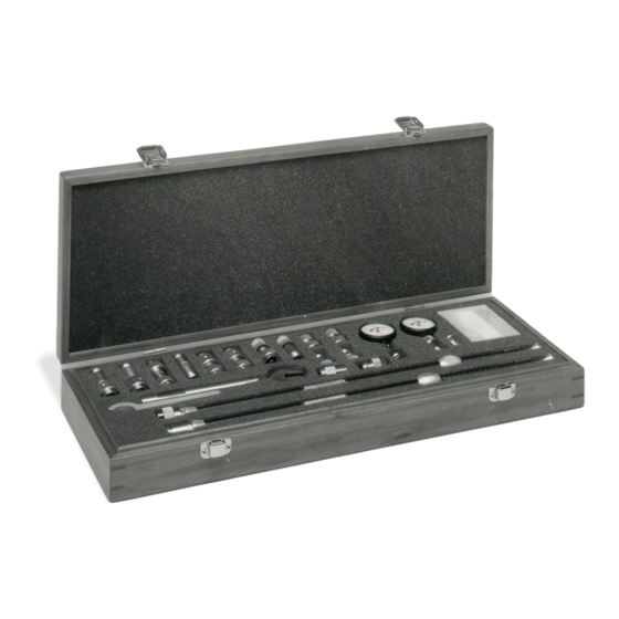
Calibration Kit Overview Calibration Kit Overview The Keysight 85054B type-N calibration kit is used to calibrate Keysight network analyzers up to 18 GHz for measurements of components with 50type-N connectors. The standards in this calibration kit allow you to perform simple 1- or 2-port and TRM (thru–reflect–match) calibrations. -
Page 9: Calibration Definitions
The calibration definitions for the kit may be permanently installed in the internal memory or hard disk of the network analyzer. If the calibration definitions for the kit are not permanently installed in the network analyzer, they must be manually entered. Refer to your network analyzer user’s guide for instructions. 85054B... -
Page 10: Equipment Required But Not Supplied
“Contacting Keysight” on page 5-5. Keysight will arrange for repair or replacement of incomplete or damaged shipments without waiting for a settlement from the transportation company. See “Returning a Kit or Device to Keysight” on page 5-4. 1- 4 85054B... -
Page 11: Serial Numbers
Record these serial numbers in Table 1-1. Recording the serial numbers will prevent confusing the devices in this kit with similar devices from other kits. Table 1-1 Serial Number Record for the 85054B Device Serial Number Calibration kit ____________________________ Calibration Devices Lowband load –m–... -
Page 12: Precision Slotless Connectors
With PSCs on test ports and standards, the percentage of accuracy achieved when measuring at 50 dB return loss levels is comparable to using conventional slotted connectors measuring devices having only 30 dB return loss. This represents an accuracy improvement of about 10 times. 1- 6 85054B... -
Page 13: Clarifying The Terminology Of A Connector Interface
Improper connections, resulting from pin depth values being out of the observed limits (see Table 2-2 on page 2-4), or from bad connections, can also damage these devices. 85054B... -
Page 14: When To Calibrate
With experience you will be able to see changes in the reference responses that indicate a need to perform the measurement calibration again. 1- 8 85054B... -
Page 15: Specifications
Specifications... -
Page 16: Environmental Requirements
During a measurement calibration, the temperature of the calibration devices must be stable and within the range specified in Table 2-1. IMPORTANT Avoid unnecessary handling of the devices during calibration because your fingers are a heat source. 2- 2 85054B... -
Page 17: Mechanical Characteristics
Mechanical characteristics such as center conductor protrusion and pin depth are not performance specifications. They are, however, important supplemental characteristics related to the electrical performance of devices. Keysight Technologies verifies the mechanical characteristics of the devices in this kit with special gaging processes and electrical testing. - Page 18 When measuring pin depth, the measured value (resultant average of three or more measurements) is not the true value. Always compare the measured value with the observed pin depth limits in Table 2-2 to evaluate the condition of device connectors. 2- 4 85054B...
-
Page 19: Electrical Specifications
Definitions Values are Available on the Web” on page A-2 Certification Keysight Technologies certifies that this product met its published specifications at the time of shipment from the factory. Keysight further certifies that its calibration measurements are traceable to the United States National Institute of Standards and Technology (NIST) to the extent allowed by the Institute's calibration facility, and to the calibration facilities of other International Standards Organization members. - Page 20 Specifications Electrical Specifications 2- 6 85054B...
-
Page 21: Use, Maintenance, And Care Of The Devices
Use, Maintenance, and Care of the Devices... -
Page 22: Electrostatic Discharge
3. Connect the other end of the cable to the test port. 4. Remove the short from the cable. Refer to Chapter 6 , “Replaceable Parts,” for part numbers and instructions for ordering ESD protection devices. Figure 3-1 ESD Protection Setup 3- 2 85054B... -
Page 23: Visual Inspection
If a connector shows deep scratches or dents, particles clinging to the mating plane surfaces, or uneven wear, clean and inspect it again. Devices with damaged connectors should be discarded. Determine the cause of damage before connecting a new, undamaged connector in the same configuration. 85054B... -
Page 24: Inspect The Precision Slotless Connectors (Female)
Refer to Table 6-2 on page 6-3 for a part number for cleaning swabs. a. Apply a small amount of isopropyl alcohol to a lint-free cleaning swab. 3- 4 85054B... - Page 25 Let the alcohol evaporate, then blow the connector dry with a gentle stream of clean, low-pressure compressed air or nitrogen. Always completely dry a connector before you reassemble or use it. 4. Inspect Inspect the connector again to make sure that no particles or residue are present. 85054B...
-
Page 26: Gaging Connectors
Use, Maintenance, and Care of the Devices Gaging Connectors Gaging Connectors The gages available from Keysight Technologies are intended for preventive maintenance and troubleshooting purposes only. (See Table 6-1 on page 6-2 for part number information.) They are effective in detecting excessive center conductor protrusion or recession, and conductor damage on DUTs, test accessories, and the calibration kit devices.Do not use the gages for... -
Page 27: When To Gage Connectors
Refer to “Pin Depth” on page 2-3 for definitions of protrusion and recession. Figure 3-2 Reading the Connector Gage 85054B... -
Page 28: Gaging Procedures
Compare the average reading with the observed pin depth limits in Table 2-2 on page 2-4. 3- 8 85054B... - Page 29 Use, Maintenance, and Care of the Devices Gaging Connectors Figure 3-3 Gaging Male Type-N Connectors 85054B...
- Page 30 Compare the average reading with the observed pin depth limits in Table 2-2 on page 2-4. 3- 10 85054B...
- Page 31 Use, Maintenance, and Care of the Devices Gaging Connectors Figure 3-4 Gaging Female Type-N Connectors 85054B 3-11...
- Page 32 9. Read the gage indicator dial. If the needle had moved clockwise, the center conductor is protruding and the value is determined by the black numbers. If the needle had moved counterclockwise, the center conductor is recessed by an amount determined by the red numbers. 3- 12 85054B...
- Page 33 The sliding load will not perform to its specifications if the centering bead is not removed from the sliding load before an electrical calibration. Figure 3-5 Gaging the Sliding Loads 85054B 3-13...
- Page 34 However, the pin depth should be rechecked before each use. Replace the protective plastic caps on the sliding load and gage connectors when these devices are not in use. 3- 14 85054B...
- Page 35 Use, Maintenance, and Care of the Devices Gaging Connectors Figure 3-6 Adjusting the Sliding Load Pin Depth 85054B 3-15...
-
Page 36: Connections
Table 3-1 Torque Wrench Information Connector Type Torque Setting Torque Tolerance Type-N 135 N-cm (12 in-lb) 13.5 N-cm (1.2 in-lb) Using a torque wrench guarantees that the connection is not too tight, preventing possible 3- 16 85054B... - Page 37 This is especially true when several devices are connected together. Figure 3-7 Wrench Positions 2. Hold the torque wrench lightly, at the end of the handle only (beyond the groove). See Figure 3-8. Figure 3-8 Using the Torque Wrench 85054B 3-17...
- Page 38 3. Release pressure on the center conductor and mate the outer conductor of the sliding load with the outer conductor of the cable/test port connector. Torque the connection with a 3/4 3- 18 85054B...
-
Page 39: How To Separate A Connection
1. Use an open-end wrench to prevent the device body from turning. 2. Use the torque wrench to loosen the connector nut. 3. Complete the separation by hand, turning only the connector nut. 4. Pull the connectors straight apart without twisting, rocking, or bending either of the connectors. 85054B 3-19... -
Page 40: Using The Sliding Load
• To view the ENA or PNA online Help, press the Help key on the front panel of the network analyzer. • To view an online VNA user guide, use the following steps: 1. Go to www.keysight.com. 2. Enter your VNA model number (Ex: N5242A) in the Search box and click Search. 3- 20 85054B... - Page 41 3. Under the heading Manuals & Guides, click on the title/hyperlink for the document PDF you want to view. If you need additional information, see “Where to Look for More Information” on page 5-3. Figure 3-10 Using the Sliding Load (Preferred Method) 85054B 3-21...
-
Page 42: Handling And Storage
• Do not set connectors contact-end down on a hard surface. The plating and the mating plane surfaces can be damaged if the interface comes in contact with any hard surface. 3- 22 85054B... -
Page 43: Performance Verification
Performance Verification... -
Page 44: Introduction
These two steps establish a traceable link to NIST for Keysight to the extent allowed by the Institute's calibration facility. The specifications data provided for the devices in this kit is traceable to NIST through Keysight Technologies. 4- 2 85054B... -
Page 45: Recertification
A list of NIST traceable numbers may be purchased upon request to be included in the calibration report. Keysight Technologies offers a Standard calibration for the recertification of this kit. For more information, contact Keysight Technologies. For contact information, see page 5-5. - Page 46 Performance Verification Recertification 4- 4 85054B...
-
Page 47: Troubleshooting
Troubleshooting... -
Page 48: Troubleshooting Process
Troubleshooting Troubleshooting Process Troubleshooting Process If you suspect a bad calibration, or if your network analyzer does not pass performance verification, follow the steps in Figure 5-1. Figure 5-1 Troubleshooting Flowchart 5- 2 85054B... -
Page 49: Where To Look For More Information
2. Enter your VNA model number (Ex: N5242A) in the Search box and click Search. 3. Under the heading Manuals & Guides, click on the title/hyperlink for the document PDF you want to view. If you need additional information, see “Contacting Keysight” on page 5-5. 85054B... -
Page 50: Returning A Kit Or Device To Keysight
Troubleshooting Returning a Kit or Device to Keysight Returning a Kit or Device to Keysight If your kit or device requires service, contact Keysight Technologies for information on where to send it. See “Contacting Keysight” on page 5-5 for contact information. Include a service tag (located near the end of this manual) on which you provide the following information: •... -
Page 51: Contacting Keysight
If you do not have access to the Internet, please contact your Keysight field engineer. NOTE In any correspondence or telephone conversation, refer to the Keysight product by its model number and full serial number. With this information, the Keysight representative can determine whether your product is still within its warranty period. 85054B... - Page 52 Troubleshooting Contacting Keysight 5- 6 85054B...
-
Page 53: Replaceable Parts
Replaceable Parts... -
Page 54: Introduction
Replaceable Parts Introduction Introduction Table 6-1 lists the replacement part numbers for items included in the 85054B calibration kit Figure 6-1 illustrates each of these items. Table 6-2 lists the replacement part numbers for items recommended or required for successful operation but not included in the calibration kit. - Page 55 Replaceable Parts Introduction Table 6-1 Replaceable Parts for the 85054B Calibration Kit Description Qty Per Kit Keysight Part Number Type-N gage master –f– 85054-60052 Type-N gage –m– 85054-60051 Type-N gage master –m– 85054-60053 Centering beads 85054-80028 Miscellaneous Items User’s and service guide 85054-90049 Protective End Cap, 0.812-ID, Black...
- Page 56 Replaceable Parts Introduction Figure 6-1 Replaceable Parts for the 85054B Calibration Kit 6- 4 85054B...
- Page 57 Replaceable Parts Introduction Figure 6-2 More Replaceable Parts for the 85054B Calibration Kit 85054B...
- Page 58 Replaceable Parts Introduction 6- 6 85054B...
-
Page 59: Standard Definitions
Standard Definitions... -
Page 60: Class Assignments And Standard Definitions Values Are Available On The Web
Keysight vector network analyzers. It also provides some examples of how to set up a new calibration kit and how to modify an existing calibration kit definition file. To download a free copy, go to www.keysight.com and enter literature number 5989-4840EN in the Search window. A- 2 85054B... - Page 61 3-10 standards master 3-10 sticker reading temperature zeroing 3-10 when to perform constants, calibration, See calibration definitions calibration kit contacting Keysight Technologies Keysight Application Note contents contents incomplete modifying definition files what to do overview center conductor protrusion recession damage...
- Page 62 & std definitions from as cleaning solvent the Web electrical specifications contents electrostatic discharge overview supplies Keysight Technologies part numbers application note when making connections 3-16 contacting environmental requirements equipment required label but not supplied...
- Page 63 3-20 connections 3-18 warranty, documentation gaging 3-12 when to calibrate in kit contents wrench pin depth open-end 3-19 adjusting 3-14 part number set marks 3-20 undoing connections 3-19 sliding ring 3-20 part numbers using 3-20 torque specifications Index- 3 85054B...
- Page 64 Index part number zeroing connector gage 3-10 3-12 Index-4 85054B...
- Page 65 This information is subject to change without notice. © Keysight Technologies 1993 - 2014 November 2014 *85054-90049* 85054-90049 www.keysight.com...
Need help?
Do you have a question about the 85054B and is the answer not in the manual?
Questions and answers