
Subscribe to Our Youtube Channel
Related Manuals for Keysight Technologies 85051B


Summary of Contents for Keysight Technologies 85051B
- Page 1 Keysight 85051B 7 mm Verification Kit This manual applies directly to 85051B Verification Kits that have serial number prefix 2815A. The verification devices in this kit are individually serialized. User's and Service Guide...
-
Page 2: Safety Notices
DOCUMENT THAT CONFLICT WITH THESE TERMS, THE WARRANTY beyond those set forth in the TERMS IN THE SEPARATE EULA shall apply, except to the © Keysight Technologies, Inc. AGREEMENT WILL CONTROL. extent that those terms, rights, or 1995-2018 licenses are explicitly required... -
Page 3: Table Of Contents
How Keysight Verifies the Devices in Your Kit ........4-1 Keysight 85051B User’s and Service Guide... - Page 4 Replaceable Parts ............6-4 Keysight 85051B User’s and Service Guide...
-
Page 5: General Information
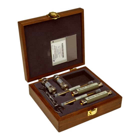
General Information Verification Kit Overview The Keysight 85051B 7 mm verification kit provides a set of standards with known characteristics, traceable to a reference (golden) standard in Keysight Technologies calibration lab. This set of standards is used to verify your measurement calibration and also to verify that your PNA system is operating within its specifications. -
Page 6: Calibration Definitions
“Contacting Keysight” on page Calibration Definitions The 85051B verification kit is intended to be used with the 85050B/C/D 7 mm calibration kits. Prior to performing a calibration with your PNA, the calibration kit must be selected and the calibration definitions for the devices in the kit installed in the PNA. -
Page 7: Recording The Device Serial Numbers
Table . Recording the serial numbers will prevent confusing the devices in this kit with similar devices from other kits. Table 1-1 Serial Number Record for the 85051B Device Serial Number Verification kit ___________________________ 20 dB attenuator... -
Page 8: Clarifying The Terminology Of A Connector Interface
Improper connections, resulting from pin depth values being out of specification (see Table 2-2 on page 3), or from bad connection techniques, can also damage these devices. 85051B... -
Page 9: Downloading The Documentation From The Web
To view the documentation on the web, use the following steps: 1. Go to www.keysight.com. 2. In the Search box, enter the model number of the analyzer (Ex: 85051B) and click Search. 3. Click Technical Support > Document Library > Manuals 4. - Page 10 General Information Downloading the Documentation from the Web 85051B...
-
Page 11: Specifications
Keysight 85051B 7 mm Verification Kit User’s and Service Guide Specifications Environmental Requirements Samples of this product have been type-tested in accordance with the Keysight Environmental Test Manual and verified to be robust against the environmental stresses of storage, transportation and end-use; those stresses include but are not limited to temperature, humidity, shock, vibration, altitude and power-line conditions. -
Page 12: Mechanical Characteristics
They are, however, important supplemental characteristics related to electrical performance. Keysight Technologies verifies the mechanical characteristics of the devices in this kit with special gaging processes and electrical testing. This ensures that the device connectors do not exhibit any improper pin depth when the kit leaves the factory. -
Page 13: Airline Mechanical Characteristics
The center and outer conductors of the airlines in this kit have been mechanically measured and matched. Do not use the center or outer conductors provided in this kit with a center or outer conductor from any other airline. Damage to the airline or attaching connector may result. 85051B... - Page 14 Dimension millimeters inches 3.04 ±0.0025 0.1197 ±0.00010 +0.0025/−0.010 +0.00010/−0.0004 ΔL Figure 2-4 25Ω Mismatch Airline Center Conductor Dimension millimeters inches 3.04 ±0.008 0.1197 ±0.0003 4.613 ±0.005 0.1816 ±0.0002 74.93 ±0.019 2.950 ±0.0007 12.514 ±0.050 0.4927 ±0.0020 ΔL +0.0025/−0.0100 +0.0001/−0.0004 85051B...
-
Page 15: Electrical Specifications
National Institute of Standards and Technology (NIST) through mechanical and electrical paths (for more information on traceability, contact Keysight Technologies. Refer to “Contacting Keysight” on page The factory-measured data for each device is supplied in print and on USB drive with your kit. 85051B... - Page 16 Specifications Electrical Specifications 85051B...
- Page 17 Keysight 85051B 7 mm Verification Kit User’s and Service Guide Use, Maintenance, and Care of the Devices Electrostatic Discharge Protection against electrostatic discharge (ESD) is essential while connecting, inspecting, or cleaning connectors attached to a static-sensitive circuit (such as those found in test sets).
-
Page 18: Use, Maintenance, And Care Of The Devices Electrostatic Discharge
Use, Maintenance, and Care of the Devices Electrostatic Discharge Figure 3-1 ESD Protection Setup 85051B... -
Page 19: Visual Inspection
Look especially for deep scratches or dents, and for dirt and metal particles on the connector mating plane surfaces. Also look for signs of damage due to excessive or uneven wear or misalignment. 85051B... - Page 20 Other small defects and cosmetic imperfections are also normal. None of these affect electrical or mechanical performance. If a connector shows deep scratches or dents, particles clinging to the mating plane surfaces, or uneven wear, clean and inspect it again. 85051B...
-
Page 21: Cleaning Connectors
Refer to Table 6-3 on page 4 a part number for cleaning swabs. a. Apply a small amount of isopropyl alcohol to a lint-free cleaning swab. b. Clean the connector threads. 85051B... - Page 22 Always completely dry a connector before you reassemble or use it. 4. Inspect Inspect the connector to make sure that no particles or residue remain. Refer to “Visual Inspection” on page 85051B...
-
Page 23: Gaging Connectors
Use, Maintenance, and Care of the Devices Gaging Connectors Gaging Connectors The gages available from Keysight Technologies are intended for preventive maintenance and troubleshooting purposes only. They are effective in detecting excessive center conductor protrusion or recession, and conductor damage on DUTs, test accessories, and the calibration kit devices. Do not use the gages for precise pin depth measurements. -
Page 24: Reading The Connector Gage
If the center conductor protrudes, the indicator will move clockwise to indicate the amount of protrusion, which is read as a positive value. Figure 3-2 Reading the Connector Gage 85051B... -
Page 25: Gaging Procedure
Read the gage indicator dial. If the needle has moved clockwise, the center conductor is protruding by an amount indicated by the black numbers. If the needle has moved counterclockwise, the center conductor is recessed by an amount indicated by the red numbers. 85051B... - Page 26 Compare the average reading with the pin depth specifications listed in Table 2-2 on page f. Remove the device from the gage. 3-10 85051B...
- Page 27 Use, Maintenance, and Care of the Devices Gaging Connectors Figure 3-3 Gaging 7 mm Connectors 85051B 3-11...
-
Page 28: Gaging The Airline
7. Insert the center conductor into the outer conductor so that the mark on the center conductor is closest to the “A” end of the outer conductor. Do not let the center conductor scrape the edge of the outer conductor or damage may result. 3-12 85051B... - Page 29 Replace the other plastic cap on the outer conductor and store the center and outer conductors in the foam lined storage case. 85051B 3-13...
-
Page 30: Making Connections
Very light finger pressure is enough to accomplish this. 10.Make sure the connectors are properly supported. Relieve any side pressure on the connection from long or heavy devices or cables. 3-14 85051B... - Page 31 This is especially true when several devices are connected together. Figure 3-6 Wrench Positions 2. Hold the torque wrench lightly, at the end of the handle only (beyond the groove). See Figure 3-7. 85051B 3-15...
-
Page 32: Connecting The Airline
OFF and take care to avoid electrostatic discharge. Refer to “Electrostatic Discharge” on page Be especially careful not to drop either the center conductor or the outer conductor when handling these airlines. Irreparable damage will result if these devices are dropped. 3-16 85051B... - Page 33 Making Connections Detachable spring-loaded tips are supplied with the center conductors of both the airline and mismatch airline in your 85051B kit. Do not use these tips when connecting the airlines to the TRL adapters supplied in the 85050C 7 mm Precision Calibration Kit.
- Page 34 7. Insert the tip of the center conductor (emerging from the “A” end) into the cable center conductor. See Figure 3-10. Mate the outer conductors of the airline and port 1 cable connector finger tight. 3-18 85051B...
- Page 35 10.Mate the outer conductors of the port 2 cable connector and airline finger tight. 11.Torque the cable connectors as shown in Figure 3-11 on page 20. To keep the airline from turning, either hold its plastic insulation or use an open end wrench while you torque the connection. 85051B 3-19...
-
Page 36: How To Separate A Connection
If disconnecting an airline and the airline center conductor does not disengage from the device center conductor, gently pull the center conductors apart and then push the airline center conductor back inside the outer conductor of the airline. 3-20 85051B... -
Page 37: Handling And Storage
— Do not set connectors contact-end down on a hard surface. The plating and the mating plane surfaces can be damaged if the interface comes in contact with any hard surface. 85051B 3-21... - Page 38 Use, Maintenance, and Care of the Devices Handling and Storage 3-22 85051B...
-
Page 39: Performance Verification
These two steps establish a traceable link to NIST for Keysight to the extent allowed by the institute’s calibration facility. The specifications data provided for the devices in the kit is traceable to NIST through Keysight Technologies. -
Page 40: Recertification
The recertification interval should begin on the date the kit is first used after the recertification date. Where to Send a Kit for Recertification Contact Keysight Technologies for information on where to send your kit for recertification. See “Contacting Keysight” on page 4. -
Page 41: Troubleshooting
Keysight 85051B 7 mm Verification Kit User’s and Service Guide Troubleshooting Troubleshooting Process If your PNA does not pass performance verification, follow the steps in Figure 5-1 to determine the cause of the failure and the correct action to take... - Page 42 Troubleshooting Troubleshooting Process Figure 5-1 Troubleshooting Flowchart 85051B...
-
Page 43: Compatible Network Analyzers
For detailed information on using a PNA, refer to the PNA Help system. To do so, press the Help key on the front panel of the PNA. If you need additional information, see “Contacting Keysight” on page 85051B... -
Page 44: Returning A Kit Or Device To Keysight
Troubleshooting Returning a Kit or Device to Keysight Returning a Kit or Device to Keysight If your kit or device requires service, contact Keysight Technologies for information on where to send it. See “Contacting Keysight” on page 4. Include a service tag (located near the end of this manual) on which you provide the following information: —... -
Page 45: Replaceable Parts
Keysight 85051B 7 mm Verification Kit User’s and Service Guide Replaceable Parts Replacing the Verification Data The verification data contains unique performance data that applies to the individual verification devices. No two devices have the same performance data. It is not a trivial matter to replace lost or damaged data, so it is important to make one or more backup copies. -
Page 46: Copying Replacement Device Verification Data To The Original Verification Data Media
All of the files (nine files: one .txt file, four .dat files, and four .unc files) you copied from the old verification device data media should be present. You now have a complete backup of the old verification device data on the new USB drive. 85051B... -
Page 47: New Verification Device Data - Transfer Process
11.Save and close the kitparts.txt file. 12.Remove the old verification device data media (floppy disk or USB) from your computer or PNA. Your new replacement device is now ready to use with your PNA. 85051B... -
Page 48: Replaceable Parts
Replaceable Parts Replaceable Parts Replaceable Parts Table 6-2 lists the replacement part numbers for items included in the 85051B verification kit. Table 6-3 lists the replacement part numbers for items not included in the verification kit that are either required or recommended for successful operation of the kit. - Page 49 Included in the 85050B and 85050C 7 mm calibration kits b. Included in the 85050B and 85050C, and 85050D 7 mm calibration kits. c. Keysight can no longer safely ship isopropyl alcohol, so customers should purchase it locally. 85051B...
- Page 50 Replaceable Parts Replaceable Parts Figure 6-1 Replaceable Parts 85051B...
- Page 51 See calibration definitions recession contacting Keysight Technologies certificate of calibration cord 85051-90031 Index...
- Page 52 Index grounding part number electrical specifications electrostatic discharge, environmental damage requirements caused by electrostatic discharge specifications device equipment required inspecting for to connectors conductive floor what to do conductive table mat damaged connectors heel strap data precautions recertification protection replacement device protection setup replacing supplies...
- Page 53 3-20 part number Keysight Technologies contacting part numbers of items in kit calibration of items not in kit intended to be used parts contents included in kit...
- Page 54 Index recording test data service threads service tag connector shipment cleaning verifying complete inspecting specifications torque wrench altitude part number operating specifications 3-15 storage traceability device of device specifications electrical troubleshooting environmental flowchart humidity pin depth USB drive temperature user’s and service guide torque wrench 3-15 part number...
- Page 55 Index zeroing connector gage 85051-90031 Index...
- Page 56 Index 85051-90031 Index...
- Page 57 Installation Note Xxxxx-xxxxx...
- Page 58 This information is subject to change without notice. © Keysight Technologies 1995-2018 Edition 1, November 2018 www.keysight.com...
Need help?
Do you have a question about the 85051B and is the answer not in the manual?
Questions and answers