Table of Contents
Advertisement
Quick Links
Advertisement
Table of Contents

Related Manuals for Keysight Technologies 85053B


Summary of Contents for Keysight Technologies 85053B
- Page 1 Keysight 85053B 3.5 mm Verification Kit User's and Service Guide...
- Page 2 DOCUMENT THAT CONFLICT WITH THESE TERMS, THE WARRANTY beyond those set forth in the TERMS IN THE SEPARATE EULA shall apply, except to the © Keysight Technologies, Inc. AGREEMENT WILL CONTROL. extent that those terms, rights, or 1995-2019 licenses are explicitly required...
-
Page 3: Table Of Contents
How to Separate a Connection ......... . . 3-20 Keysight 85053B User’s and Service Guide... - Page 4 Replaceable Parts ............6-4 Keysight 85053B User’s and Service Guide...
-
Page 5: General Information
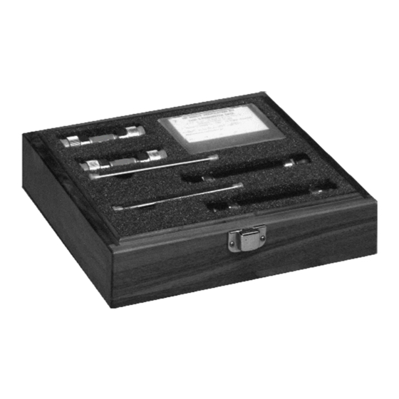
General Information Verification Kit Overview The Keysight 85053B 3.5 mm verification kit provides a set of standards with known characteristics, traceable to a reference (golden) standard in Keysight Technologies calibration lab. This set of standards is used to verify your measurement calibration and also to verify that your network analyzer system is operating within its specifications. -
Page 6: Calibration Definitions
Incoming Inspection Calibration Definitions The 85053B verification kit is intended to be used with the 85033E and 85052B 3.5 mm calibration kits. Prior to performing a calibration with your network analyzer, the calibration kit must be selected and the calibration definitions for the devices in the kit installed in the network analyzer. -
Page 7: Recording The Device Serial Numbers
Table 1-1. Recording the serial numbers will prevent confusing the devices in this kit with similar devices from other kits. Table 1-1 Serial Number Record for the 85053B Device Serial Number Verification kit ___________________________ 20 dB attenuator... -
Page 8: Precision Slotless Connectors
For this reason PSC test port adapters are supplied in most Keysight Technologies calibration kits. Precision slotless connectors have the following characteristics: —... -
Page 9: Clarifying The Terminology Of A Connector Interface
Improper connections, resulting from pin depth values being out of specification (see Table 2-2 on page 4), or from bad connection techniques, can also damage these devices. 85053B... - Page 10 General Information Preventive Maintenance 85053B...
-
Page 11: Specifications
Keysight 85053B 3.5 mm Verification Kit User’s and Service Guide Specifications Environmental Requirements Samples of this product have been type-tested in accordance with the Keysight Environmental Test Manual and verified to be robust against the environmental stresses of storage, transportation and end-use; those stresses include but are not limited to temperature, humidity, shock, vibration, altitude and power-line conditions. - Page 12 Specifications Environmental Requirements IMPORTANT! Avoid unnecessary handling the devices during use because your fingers are a heat source. 85053B...
-
Page 13: Mechanical Characteristics
This condition will indicate a positive value on the connector gage. Recession is the condition in which the center conductor is set back from the outer conductor mating plane. This condition will indicate a negative value on the connector gage. 85053B... -
Page 14: Airline Mechanical Characteristics
In this case, the center conductor is 0.0001 inch (0.0025 mm) longer than the outer conductor. Airline Mechanical Characteristics The dimensions of the airline outer conductor are shown in Figure 2-2. This outer conductor is common to both airlines. Two conductors are provided with the kit. 85053B... - Page 15 Figure 2-2 Airline Outer Conductor Table 2-3 Dimension millimeters inches 3.500 ±0.004 0.13780 ±0.00016 74.924 ±0.025 2.950 ±0.001 Figure 2-3 50Ω Airline Center Conductor Table 2-4 Dimension millimeters inches 1.520 ±0.003 0.0598 ±0.0001 +0.0025 το –0.0100 +0.0001 to –0.0004 ΔL 85053B...
-
Page 16: Electrical Specifications
These factory measurements are traceable to the National Institute of Standards and Technology (NIST) through mechanical and electrical paths (for more information on traceability, contact Keysight Technologies. Refer to “Contacting Keysight” on page 4 for a list of contacts. - Page 17 Keysight 85053B 3.5 mm Verification Kit User’s and Service Guide Use, Maintenance, and Care of the Devices Electrostatic Discharge Protection against electrostatic discharge (ESD) is essential while connecting, inspecting, or cleaning connectors attached to a static-sensitive circuit (such as those found in test sets).
-
Page 18: Use, Maintenance, And Care Of The Devices Electrostatic Discharge
Use, Maintenance, and Care of the Devices Electrostatic Discharge Figure 3-1 ESD Protection Setup 85053B... -
Page 19: Visual Inspection
See Figure 2-1 on page 4. Look especially for deep scratches or dents, and for dirt and metal particles on the connector mating plane surfaces. Also look for signs of damage due to excessive or uneven wear or misalignment. 85053B... -
Page 20: Inspect Female Connectors
The precision slotless connector was developed to eliminate this problem. The PSC has a center conductor with a solid cylindrical shell, the outside diameter of which does not change when mated. Instead, this center conductor has an internal contact that flexes to accept the male pin. 85053B... -
Page 21: Cleaning Connectors
Refer to Table 6-3 on page 5 a part number for cleaning swabs. a. Apply a small amount of isopropyl alcohol to a lint-free cleaning swab. b. Clean the connector threads. 85053B... - Page 22 Always completely dry a connector before you reassemble or use it. 4. Inspect Inspect the connector to make sure that no particles or residue remain. Refer to “Visual Inspection” on page 85053B...
-
Page 23: Gaging Connectors
Use, Maintenance, and Care of the Devices Gaging Connectors Gaging Connectors The gages available from Keysight Technologies are intended for preventive maintenance and troubleshooting purposes only. They are effective in detecting excessive center conductor protrusion or recession, and conductor damage on DUTs, test accessories, and the calibration kit devices. Do not use the gages for precise pin depth measurements. - Page 24 Use, Maintenance, and Care of the Devices Gaging Connectors — Initially after every 100 connections, and after that as often as experience indicates. 85053B...
-
Page 25: Gaging Procedures
Torque Wrench” on page 17 for additional information. c. Gently tap the barrel of the gage with your finger to settle the gage reading. d. Read the gage indicator dial. Read only the black ± signs; not the red ± signs. 85053B... - Page 26 Compare the average reading with the observed pin depth limits in Table 2-2 on page 3-10 85053B...
- Page 27 Use, Maintenance, and Care of the Devices Gaging Connectors Figure 3-2 Gaging 3.5 mm Connectors 85053B 3-11...
-
Page 28: Gaging The Airline
Tighten the dial lock screw. e. Without turning the short or the gage, remove the short from the gage. Refer to “How to Separate a Connection” on page 3-12 85053B... - Page 29 Insert the center conductor into the outer conductor so that the female end of the center conductor is toward the female end of the outer conductor (the end without the connector nut). Refer to Figure 3-4. 85053B 3-13...
- Page 30 Refer to “Final Connection Using a Torque Wrench” on page 17 for additional information. c. Gently tap the barrel of the gage with your finger to settle the gage reading. 3-14 85053B...
- Page 31 Replace the other protective end cap on the outer conductor and store the center and outer conductors in the foam lined storage case. 85053B 3-15...
-
Page 32: Connections
Very light finger pressure is enough to accomplish this. 8. Make sure the connectors are properly supported. Relieve any side pressure on the connection from long or heavy devices or cables. 3-16 85053B... -
Page 33: Final Connection Using A Torque Wrench
This is especially true when several devices are connected together. Figure 3-6 Wrench Positions 2. Hold the torque wrench lightly, at the end of the handle only (beyond the groove). See Figure 3-7. 85053B 3-17... -
Page 34: Connecting The Airline
1. Remove the center conductor from its plastic case. Make sure you select the correct center conductor for the airline you are connecting. Refer to Figure 2-3 Figure 2-4 on page 6 for illustrations of both center conductors. 3-18 85053B... - Page 35 5. Bring the airline—with center conductor installed—toward the cable connector and mate the female end of the airline center conductor with the center conductor of the cable connector. Refer to Figure 3-9. Figure 3-9 Connecting the Airline 85053B 3-19...
-
Page 36: How To Separate A Connection
1. Use an open-end wrench to prevent the device body from turning. 2. Use another open-end wrench to loosen the connector nut. 3. Complete the disconnection by hand, turning only the connector nut. 3-20 85053B... -
Page 37: Handling And Storage
— Do not set connectors contact-end down on a hard surface. The plating and the mating plane surfaces can be damaged if the interface comes in contact with any hard surface. 85053B 3-21... - Page 38 Use, Maintenance, and Care of the Devices Handling and Storage 3-22 85053B...
-
Page 39: Performance Verification
These two steps establish a traceable link to NIST for Keysight to the extent allowed by the institute’s calibration facility. The specifications data provided for the devices in the kit is traceable to- NIST through Keysight Technologies. 4- 1... -
Page 40: Recertification
The recertification interval should begin on the date the kit is first used after the recertification date. Where to Send a Kit for Recertification Contact Keysight Technologies for information on where to send your kit for recertification. See “Contacting Keysight” on page 4. Refer to “Returning a Kit... -
Page 41: Troubleshooting
Keysight 85053B 3.5 mm Verification Kit User’s and Service Guide Troubleshooting Troubleshooting Process If your network analyzer does not pass performance verification, follow the steps in Figure 5-1 to determine the cause of the failure and the correct action to take to correct the failure. - Page 42 Troubleshooting Troubleshooting Process Figure 5-1 Troubleshooting Flowchart 85053B...
-
Page 43: Compatible Network Analyzers
When old verification kits that include the data disks are returned to Keysight for recertification, the disks will be reproduced with new data for each device in the kit. Please specify your VNA model(s) when returning kits for service or when ordering kit replacement parts. 85053B... -
Page 44: Where To Look For More Information
If you need additional information, see “Contacting Keysight” on page Returning a Kit or Device to Keysight If your kit or device requires service, contact Keysight Technologies for information on where to send it. See “Contacting Keysight” on page 4. Include... -
Page 45: Replaceable Parts
Keysight 85053B 3.5 mm Verification Kit User’s and Service Guide Replaceable Parts Replacing the Verification Data The verification data contains unique performance data that applies to the individual verification devices. No two devices have the same performance data. It is not a trivial matter to replace lost or damaged data, so it is important to make one or more backup copies. -
Page 46: Copying Replacement Device Verification Data To The Original Verification Data Media
All of the files (nine files: one .txt file, four .dat files, and four .unc files) you copied from the old verification device data media should be present. You now have a complete backup of the old verification device data on the new USB drive. 85053B... -
Page 47: New Verification Device Data - Transfer Process
11. Save and close the kitparts.txt file. 12. Remove the old verification device data media (floppy disk or USB) from your computer or PNA. Your new replacement device is now ready to use with your PNA. 85053B... -
Page 48: Replaceable Parts
Replaceable Parts Replaceable Parts Replaceable Parts Table 6-2 lists the replacement part numbers for items included in the 85053B verification kit. Table 6-3 lists the replacement part numbers for items not included in the verification kit that are either required or recommended for successful operation of the kit. - Page 49 Included in the 85033E 3.5 mm calibration kit. “Precision Slotless Con- c. All female connectors on the precision devices in this kit are slotless connectors. Refer to nectors” on page 4 d. Keysight can no longer safely ship isopropyl alcohol, so customers should purchase it locally. 85053B...
- Page 50 Replaceable Parts Replaceable Parts Figure 6-1 Component Identification Sheet 85053B...
- Page 51 See calibration definitions cleaning supplies contacting Keysight Technologies 85053-90028 Index...
- Page 52 Index contents disconnections 3-20 drawing of verification kit electrical specifications cord electrostatic discharge, grounding environmental part number regulations requirements damage specifications caused by electrostatic discharge equipment required device inspecting for conductive floor to connectors conductive table mat what to do heel strap damaged connectors precautions...
- Page 53 Keysight Technologies open-end wrench 3-20 contacting options ordering parts calibration intended to be used contents part numbers drawing of...
- Page 54 Index recession, pin depth wrist regulations part number environmental supplemental characteristics replaceable parts supplies drawing of cleaning replacement device data report, calibration table mat requirements for ESD protection environmental return kit or device to Keysight service temperature separating connections 3-20 affect on electrical performance serial numbers calibration...
- Page 55 Index overview performance how Keysight verifies verifying visual inspection wear connector affect on electrical performance wrench open-end 3-17 3-20 part number proper positioning of 3-17 torque 3-17 3-18 part number precautions for use of 3-18 proper use of 3-18 wrist strap for ESD protection part number zeroing...
- Page 56 Index 85053-90028 Index...
- Page 57 Installation Note Xxxxx-xxxxx...
- Page 58 This information is subject to change without notice. © Keysight Technologies 1995-2021 Edition 1, May 2021 www.keysight.com...
Need help?
Do you have a question about the 85053B and is the answer not in the manual?
Questions and answers