Table of Contents
Advertisement
Quick Links
Advertisement
Table of Contents

Related Manuals for Keysight Technologies 85033E


Summary of Contents for Keysight Technologies 85033E
- Page 1 Keysight 85033E 3.5mm Calibration Kit User’s and Service Manual...
- Page 2 THESE TERMS, THE WARRANTY TERMS IN THE SEPARATE EULA shall apply, except to the AGREEMENT WILL CONTROL. extent that those terms, rights, or © Keysight Technologies, Inc. licenses are explicitly required Technology Licenses 2000-2017 from all providers of commercial No part of this manual may be...
-
Page 3: Table Of Contents
How to Make a Connection ..........3-14 Keysight 85033E User’s and Service Guide... - Page 4 Introduction ............. . . 6-1 A:.Standard Definitions Class Assignments and Standard Definitions Values are Available on the Web ..A-1 Keysight 85033E User’s and Service Guide...
-
Page 5: General Information
3.5 mm Calibration Kit User’s and Service Guide General Information Calibration Kit Overview The Keysight 85033E 3.5 mm calibration kit is used to calibrate Keysight network analyzers for measurements of components with 3.5 mm connectors up to 9 GHz. Kit Contents Use the Contents List in the shipping container to verify the completeness of your shipment. -
Page 6: Calibration Definitions
— downloaded from the Web at http:na.support.keysight.com/pna/caldefs/stddefs.html — manually entered from the front panel Refer to your network analyzer user’s guide or embedded Help for instructions on manually entering calibration definitions, selecting the calibration kit, and performing a calibration. Keysight 85033E User’s and Service Guide... -
Page 7: Options
General Information Incoming Inspection Options There are several adapter options available for the 85033E. Refer to Table 6-2 on page 6-4. Also, there are calibration certificate options available. Contact Keysight for more information. See “Contacting Keysight” on page 5-4 contact information. -
Page 8: Recording The Device Serial Numbers
Table 1-1 Kit and Device Serial Number Record Device Serial Number Calibration kit _______________________________ -m- Broadband Load _______________________________ -f- Broadband Load _______________________________ -m- Open _______________________________ -f- Open _______________________________ -m- Short _______________________________ -f- Short _______________________________ Keysight 85033E User’s and Service Guide... -
Page 9: Precision Slotless Connectors
With PSCs on test ports and standards, the percentage of accuracy achieved when measuring at 50 dB return loss levels is comparable to using conventional slotted connectors measuring devices having only 30 dB return loss. This represents an accuracy improvement of about 10 times. Keysight 85033E User’s and Service Guide... -
Page 10: Clarifying The Terminology Of A Connector Interface
Improper connections, resulting from pin depth values being out of the observed limits (see Table 2-3 on page 2-3) or from bad connection techniques, can also damage these devices. Keysight 85033E User’s and Service Guide... -
Page 11: When To Calibrate
With experience you will be able to see changes in the reference responses that indicate a need to perform the measurement calibration again. Keysight 85033E User’s and Service Guide... - Page 12 General Information When to Calibrate Keysight 85033E User’s and Service Guide...
-
Page 13: Specifications
Keysight 85033E 3.5 mm Calibration Kit User’s and Service Guide Specifications Environmental Requirements Table 2-1 Environmental Requirements Parameter Limits Temperature +15 C to +35 C Operating Storage 40 C to +75 C Error-corrected range 1 C of measurement calibration temperature Type tested, 0% to 95%, 40 C (non-condensing) -
Page 14: Mechanical Characteristics
If the pin depth of a device does not measure within the observed pin depth limits, it may be an indication that the device fails to meet electrical specifications. Refer to Figure 2-1 for a visual representation of proper pin depth (slightly recessed). Keysight 85033E User’s and Service Guide... - Page 15 Approximately +2 sigma to 2 sigma of gage uncertainty based on studies done at the factory according to recommended procedures. b. Observed pin depth limits are the range of observation limits seen on the gage reading due to measurement uncertainty. The depth could still be within specifications. Keysight 85033E User’s and Service Guide...
-
Page 16: Electrical Specifications
0.55 from Nominal >3 to 6 0.65 from Nominal >6 to 9 a. The specifications for the opens and shorts are given as allowed deviation from the nominal model as defined in the standard definitions. Keysight 85033E User’s and Service Guide... -
Page 17: Supplemental Characteristics
Return Loss 28d0.040) DC to 18 Certification Keysight Technologies certifies that this product met its published specifications at the time of shipment from the factory. Keysight further certifies that its calibration measurements are traceable to the United States National Institute of Standards and Technology (NIST) to the extent allowed by the Institute's calibration facility, and to the calibration facilities of other International Standards Organization members. - Page 18 Specifications Electrical Specifications Keysight 85033E User’s and Service Guide...
- Page 19 3. Connect the other end of the cable to the test port. 4. Remove the short from the cable. Refer to Chapter 6, “Replaceable Parts.” for part numbers and instructions for ordering ESD protection devices. Keysight 85033E User’s and Service Guide3-1...
-
Page 20: Use, Maintenance, And Care Of The Devices Electrostatic Discharge
Use, Maintenance, and Care of the Devices Electrostatic Discharge Figure 3-1 ESD Protection Setup Keysight 85033E User’s and Service Guide... -
Page 21: Visual Inspection
Other small defects and cosmetic imperfections are also normal. None of these affect electrical or mechanical performance. If a connector shows deep scratches or dents, particles clinging to the mating plane surfaces, or uneven wear, clean and inspect it again. Keysight 85033E User’s and Service Guide... -
Page 22: Inspect Female Connectors
A connector with damaged contact fingers will not make good electrical contact and must be replaced. This is particularly important when you are mating nonprecision to precision devices. Keysight 85033E User’s and Service Guide... -
Page 23: Cleaning Connectors
Refer to Table 6-3 on page 6-4 for a cleaning swab part number. a. Apply a small amount of isopropyl alcohol to the lint-free cleaning swab. b. Clean the connector threads. Keysight 85033E User’s and Service Guide... - Page 24 Always completely dry a connector before you reassemble or use it. 4. Inspect Each Connector Inspect the connector again to make sure that no particles or residue are present. Keysight 85033E User’s and Service Guide...
-
Page 25: Gaging Connectors
Use, Maintenance, and Care of the Devices Gaging Connectors Gaging Connectors The gages available from Keysight Technologies (see Table 6-3 on page 6-4 part number information) are intended for preventive maintenance and troubleshooting purposes only. They are effective in detecting excessive center conductor protrusion or recession, and conductor damage on DUTs, test accessories, and the calibration kit devices.Do not use the gages for precise... -
Page 26: When To Gage Connectors
If not, adjust the zero set knob until the gage pointer lines up exactly with zero. d. Remove the gage master. 4. Gage the device connector (refer to Figure 3-3 on page 3-10): Keysight 85033E User’s and Service Guide... - Page 27 Compare the average reading with the observed pin depth limits in Table 2-3 on page 2-3. Keysight 85033E User’s and Service Guide...
- Page 28 Use, Maintenance, and Care of the Devices Gaging Connectors Figure 3-3 Gaging Male 3.5 mm Connectors 3-10 Keysight 85033E User’s and Service Guide...
-
Page 29: Gaging Female 3.5 Mm Connectors
Read the gage indicator dial. Read only the black signs;not the red signs. For maximum accuracy, measure the connector a minimum of three times and take an average of the readings. Use different orientations of the gage within the connector. After each Keysight 85033E User’s and Service Guide 3-11... - Page 30 Compare the average reading with the observed pin depth limits in Table 2-3 on page 2-3. 3-12 Keysight 85033E User’s and Service Guide...
- Page 31 Use, Maintenance, and Care of the Devices Gaging Connectors Figure 3-4 Gaging Female 3.5 mm Connectors Keysight 85033E User’s and Service Guide 3-13...
-
Page 32: Connections
Very light finger pressure is enough. 8. Make sure the connectors are properly supported. Relieve any side pressure on the connection from long or heavy devices or cables. 3-14 Keysight 85033E User’s and Service Guide... -
Page 33: Final Connection Using A Torque Wrench
Wrenches opposing each other (greater than 90 degrees apart) will cause a lifting action that can misalign and stress the connections of the device involved This is especially true when several devices are connected together. See Figure 3-5. Figure 3-5 Wrench Positions Keysight 85033E User’s and Service Guide 3-15... - Page 34 Do not twist the head of the wrench relative to the outer conductor mating plane. If you do, you apply more than the recommended torque. 3-16 Keysight 85033E User’s and Service Guide...
-
Page 35: How To Separate A Connection
1. Use an open-end wrench to prevent the device body from turning. 2. Use another open-end wrench to loosen the connector nut. 3. Complete the separation by hand, turning only the connector nut. 4. Pull the connectors straight apart without twisting, rocking, or bending. Keysight 85033E User’s and Service Guide 3-17... -
Page 36: Handling And Storage
— Do not set connectors contact-end down on a hard surface. The plating and the mating plane surfaces can be damaged if the interface comes in contact with any hard surface. 3-18 Keysight 85033E User’s and Service Guide... -
Page 37: Performance Verification
Introduction The performance of your calibration kit can only be verified by returning the kit to Keysight Technologies for recertification. The equipment required to verify the specifications of the devices inside the kit has been specially manufactured and is not commercially available. -
Page 38: Recertification
The recertification interval should begin on the date the kit is first used after the recertification date. Where to Send a Kit for Recertification Contact Keysight Technologies for information on where to send your kit for recertification. For contact information, see “Contacting Keysight” on page 5-4. -
Page 39: Troubleshooting
3.5 mm Calibration Kit User’s and Service Guide Troubleshooting Troubleshooting Process If you suspect a bad calibration, or if your network analyzer does not pass performance verification, follow the steps in Figure 5-1. Figure 5-1 Troubleshooting Flowchart Keysight 85033E User’s and Service Guide5-1... -
Page 40: Where To Look For More Information
2. Enter your VNA model number (Ex: 8753ES) in the Search box and click Search. 3. Under the heading Manuals, click on the title/hyperlink for the document PDF you want to view. If you need additional information, see “Contacting Keysight” on page 5-4. Keysight 85033E User’s and Service Guide... -
Page 41: Returning A Kit Or Device To Keysight
Troubleshooting Returning a Kit or Device to Keysight Returning a Kit or Device to Keysight If your kit or device requires service, contact Keysight Technologies for information on where to send it. See “Contacting Keysight” on page 5-4. Include a service tag (found at the end of this manual) on which you provide the following information: —... -
Page 42: Contacting Keysight
In any correspondence or telephone conversation, refer to the Keysight product by its model number and full serial number. With this information, the Keysight representative can determine whether your product is still within its warranty period. Keysight 85033E User’s and Service Guide... -
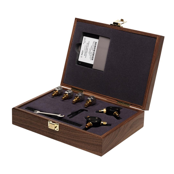
Page 43: Replaceable Parts
To order a listed part, note the description, the part number, and the quantity desired. Telephone or send your order to Keysight Technologies. For contact information, see “Contacting Keysight” on page 5-4. - Page 44 Replaceable Parts Introduction Figure 6-1 Replaceable Parts for the 85033E Calibration Kit Keysight 85033E User’s and Service Guide...
- Page 45 Part numbers in italic typeface are for production assemblies and cannot be ordered by customers. Both the replacement part number and the production part number are interchangeable and have identical performance. “Printing Copies of Documentation from the Web” on page 1-ii c. See Keysight 85033E User’s and Service Guide...
- Page 46 5 ft. grounding cord for wrist strap 9300-0980 2 x 4 ft. conductive table mat and 15 ft. ground wire 9300-0797 ESD heel strap 9300-1308 a. Keysight can no longer safely ship isopropyl alcohol, so customers should purchase it locally. Keysight 85033E User’s and Service Guide...
-
Page 47: A:.standard Definitions
It also provides some examples of how to set up a new calibration kit and how to modify an existing calibration kit definition file. To download a free copy, go to www.keysight.com and enter literature number 5989-4840EN in the Search window. Keysight 85033E User’s and Service Guide-1... - Page 48 Standard Definitions Class Assignments and Standard Definitions Values are Available on the Web Keysight 85033E User’s and Service Guide...
- Page 49 3-15 incoming disconnections 3-15 connector mating plane downloading class cleaning slotted connectors assignments & std defective visual definitions from the Web female 3-11 gaging when to do Keysight Technologies male application note electrical characteristics Keysight 85033E User’s and Service Guide...
- Page 50 3-14 traceability troubleshooting recertification Keysight 85033E User’s and Service Guide...
- Page 52 This information is subject to change without notice. © Keysight Technologies 2000 - 2014 September 2014 *85033-90028* 85033-90028 www.keysight.com...
Need help?
Do you have a question about the 85033E and is the answer not in the manual?
Questions and answers