Table of Contents
Advertisement
Quick Links
Advertisement
Table of Contents
Troubleshooting

Related Manuals for Keysight Technologies 85058E


Summary of Contents for Keysight Technologies 85058E
- Page 1 Keysight Technologies 85058B/E 1.85 mm Calibration Kits User’s and Service Guide...
- Page 2 85058B/E...
- Page 3 Limited Rights as defined in FAR 52.227-14 (June 1987) or DFAR 252.227-7015 (b)(2) (November 1995), as applicable in any technical data. Assistance Product maintenance agreements and other customer assistance agreements are available for Keysight products. For any assistance, contact Keysight Technologies. Refer to “Contacting Keysight” on page 5. 85058B/E...
- Page 4 Printing Copies of Documentation from the Web To print copies of documentation from the Web, download the PDF file from the Keysight web site: • Go to www.keysight.com. • Enter the document’s part number (located on the title page) in the Search box. •...
-
Page 5: Table Of Contents
85058E (Economy) Kit Contents ........ - Page 6 Contents How Keysight Verifies the Devices in This Kit ........4-2 Recertification .
-
Page 7: General Information
General Information... -
Page 8: Calibration Kit Overview
Calibration Kit Overview Calibration Kit Overview The Keysight 85058B (Standard) and 85058E (Economy) 1.85 mm calibration kits are used to calibrate Keysight network analyzers up to 67 GHz for measurements of components with 1.85 mm connectors. The 1.85 mm connector is designed such that it may be mated with 2.4 mm connectors. -
Page 9: 1.85 Mm Calibration Techniques
If you are using a PNA, it is RECOMMENDED that you use Expanded Math with the 85058B data-based model for the highest accuracy. Expanded Math has no effect with the 85058E data-based model. Polynomial Model The polynomial models may be used with SmartCal (Guided) and the Unguided Mechanical Calibration method of the PNA Cal Wizard. -
Page 10: 85058B (Standard) Kit Contents
General Information Calibration Kit Overview 85058E Data-Based.ckt 85058EP Polynomial.ckt ❏ OSL ❏ “Broadband” definition of broadband termination, open, and Short 1 85058B (Standard) Kit Contents The 85058B (Standard) calibration kit contains the following: • one pair (male and female) of an offset open •... -
Page 11: 85058E (Economy) Kit Contents
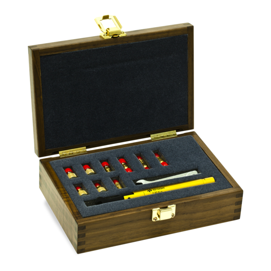
Like the other devices in the kit, the adapters are built to very tight tolerances to provide good broadband performance and to ensure stable, repeatable connections. 85058E (Economy) Kit Contents The 85058E (Economy) calibration kit contains the following: • one pair (male and female) of an offset open, offset short, and a broadband termination • three adapters •... -
Page 12: Calibration Definitions
Equipment Required but Not Supplied Gage sets (not provided with the 85058E), adapters, ESD protection devices, and various connector cleaning supplies are not included in the calibration kit but are required to ensure successful operation of the calibration kit. Refer to... -
Page 13: Achieving Specified Frequency Performance
General Information Achieving Specified Frequency Performance Achieving Specified Frequency Performance The standards in this calibration kit allow you to perform 1- or 2-port and TRM (thru-reflect-match) calibrations. NOTE For best results, before beginning calibration refer to “Clarifying the Terminology of a Connector Interface” on page 1-20. -
Page 14: Broadband Solt Calibration Using The 85058E (Economy) Calibration Kit
Achieving Specified Frequency Performance Broadband SOLT Calibration Using the 85058E (Economy) Calibration Kit The Broadband SOLT calibration is the only calibration technique available with the 85058E (Economy) kit. You can calibrate from DC to 67 GHz using the standards in Table 1-2. -
Page 15: Network Analyzer Calibrations
General Information Network Analyzer Calibrations Network Analyzer Calibrations To calibrate a Network Analyzer, use the following combinations of standards listed in Table 1-3 Table 1-4 (for 1-port calibrations), and Table 1-5 Table 1-6 (for 2-port calibrations) for the best results. For more information, refer to Table 1-1 on page 1-7 Table 1-2 on page 1-8. - Page 16 General Information Network Analyzer Calibrations Table 1-4 85058E (Economy) 1-Port Calibration Frequency Calibration Calibration Standard Range Type Standards Numbers PNA File Names: 85058E Data-Based.ckt 85058EP Polynomial.ckt DC to Open Open 2, 4 67 GHz Short Short 1 1, 3 Load...
- Page 17 General Information Network Analyzer Calibrations Table 1-5 85058B (Standard) 2-Port Calibration Frequency Calibration Calibration Standard Range Type Standards Numbers PNA File Names: 85058B Data-Based.ckt 85058BP Polynomial.ckt DC to Open Open 2, 4 35 GHz Short Short 1 1, 3 Load Load 9, 24 Thru...
- Page 18 General Information Network Analyzer Calibrations Table 1-6 85058E (Economy) 2-Port Calibration Frequency Calibration Calibration Standard Range Type Standards Numbers PNA File Names: 85058E Data-Based.ckt 85058EP Polynomial.ckt DC to Open Open 2, 4 67 GHz Short Short 3 1, 3 Load...
-
Page 19: Calibration Residual Error Specifications
General Information Calibration Residual Error Specifications Calibration Residual Error Specifications Please download our free Vector Network Analyzer Uncertainty Calculator from http://www.keysight.com/find/na_calculator. Table 1-7 85058B (Standard) Residual System Calibration Error Specifications Parameter Frequency Residuals Range Method Data-Based Data-Based Model Polynomial Model Model Expanded Math Expanded Math... - Page 20 General Information Calibration Residual Error Specifications Table 1-7 (Continued) 85058B (Standard) Residual System Calibration Error Parameter Frequency Residuals Range Method Data-Based Data-Based Model Polynomial Model Model Expanded Math Expanded Math Expanded Math Unselected Unselected Selected 2 to 0.010 0.012 0.017 10 GHz 10 to 0.033...
- Page 21 General Information Calibration Residual Error Specifications Table 1-8 85058E (Economy) Residual System Calibration Error Specifications Parameter Frequency Residuals Range Method PNA Data-Based PNA Polynomial Model Model Directivity DC to 2 GHz 2 to 10 GHz 10 to 20 GHz 20 to...
-
Page 22: Incoming Inspection
60 GHz 60 to 0.055 0.055 67 GHz a. Expanded Math has no effect with the 85058E data-based model or the 85058EP polynomial model. b. Refer to “Two Models for Defining Calibration Standards” on page 1-2. c. Using the 85058E Data-Based.ckt (PNA) calibration definitions file. -
Page 23: Recording The Device Serial Numbers
Record these serial numbers in Table 1-9 for the 85058B (Standard) and Table 1-9 for the 85058E (Economy). Recording the serial numbers will prevent confusing the devices in this kit with similar devices in other kits. Table 1-9 Serial Number Record for 85058B (Standard) - Page 24 General Information Recording the Device Serial Numbers Table 1-10 Serial Number Record for 85058E (Economy) Device Serial Number Calibration kit _______________________________ Broadband termination –m– _______________________________ Broadband termination –f– _______________________________ Open –m– _______________________________ Open –f– _______________________________ 5.4 mm offset short –m–...
-
Page 25: Slotted Connectors
General Information Slotted Connectors Slotted Connectors The female connectors in this kit have slotted contacts. Therefore, the female devices are instrument grade. Unlike precision slotless connectors, the slotted contacts prevent the devices from being classified as metrology grade. With slotted connectors, the connected male device partially determines the connector impedance of the female device by flaring the contact fingers and consequently varying the diameter of the female center conductor. -
Page 26: Clarifying The Terminology Of A Connector Interface
General Information Clarifying the Terminology of a Connector Interface Clarifying the Terminology of a Connector Interface In this document and in the prompts of the PNA calibration wizard, the sex of cable connectors and adapters is referred to in terms of the center conductor. For example, a connector or device designated as 1.85 mm –f–... -
Page 27: When To Calibrate
General Information When to Calibrate When to Calibrate A network analyzer calibration remains valid as long as the changes in the systematic error are insignificant. This means that changes to the uncorrected leakages (directivity and isolation), mismatches (source match and load match), and frequency response of the system are small (<10%) relative to accuracy specifications. - Page 28 General Information When to Calibrate 1- 22 85058B/E...
-
Page 29: Specifications
Specifications... -
Page 30: Environmental Requirements
Specifications Environmental Requirements Environmental Requirements Table 2-1 Environmental Requirements Parameter Limits +20 C to +26 C (+68 F to +79 F) Operating temperature 1 C of measurement calibration temperature Error-corrected temperature range 40 C to +75 C (40 F to +167 F) Storage temperature Relative humidity Type tested, 0% to 95% at 40C, non-condensing... -
Page 31: Mechanical Characteristics
Mechanical characteristics such as center conductor protrusion and pin depth are not performance specifications. They are, however, important supplemental characteristics related to electrical performance. Keysight Technologies verifies the mechanical characteristics of the devices in this kit with special gaging processes and electrical testing. This ensures that the device connectors do not exhibit any improper pin depth when the kit leaves the factory. -
Page 32: Electrical Specifications
Specifications Electrical Specifications its pin depth. The electrical specifications for each device in the kit take into account the effect of pin depth on the device’s performance. Table 2-2 on page 2-4 lists the typical pin depths and measurement uncertainties, and provides observed pin depth limits for the devices in the kit. If the pin depth of a device does not measure within the observed pin depth limits, it may be an indication that the device fails to meet electrical specifications. - Page 33 Specifications Electrical Specifications Table 2-3 85058B (Standard) Electrical Specifications for 1.85 mm Devices Device Frequency Parameter Specifications Male Female Polynomial Data-Based Polynomial Data-Based Model Model Model Model Lowband DC to Return Loss load 10 GHz (dB) 10 to 20 GHz 20 to 35 GHz 35 to...
- Page 34 Specifications Electrical Specifications (Continued) 85058B (Standard) Electrical Specifications for 1.85 mm Devices Table 2-3 Device Frequency Parameter Specifications Male Female Polynomial Data-Based Polynomial Data-Based Model Model Model Model 50 to 67 GHz Short 2 DC to Deviation 20 GHz from Nominal Phase (degrees) 20 to...
- Page 35 Specifications Electrical Specifications (Continued) 85058B (Standard) Electrical Specifications for 1.85 mm Devices Table 2-3 Device Frequency Parameter Specifications Male Female Polynomial Data-Based Polynomial Data-Based Model Model Model Model 20 to 30 GHz 30 to 35 GHz 35 to 40 GHz 40 to 50 GHz 50 to...
- Page 36 Specifications Electrical Specifications Table 2-4 85058E (Economy) Electrical Specifications for 1.85 mm Devices Device Frequency Parameter Specifications Male Female Polynomial Data-Based Polynomial Data-Based Model Model Model Model Broadband DC to Return Loss Termination 35 GHz (dB) 35 to 67 GHz...
-
Page 37: Certification
50 to 67 GHz Certification Keysight Technologies certifies that this product met its published specifications at the time of shipment from the factory. Keysight further certifies that its calibration measurements are traceable to the United States National Institute of Standards and Technology (NIST) to the extent allowed by the institute’s calibration facility, and to the calibration facilities of other... - Page 38 Specifications Electrical Specifications 2- 10 85058B/E...
-
Page 39: Use, Maintenance, And Care Of The Devices
Use, Maintenance, and Care of the Devices... -
Page 40: Electrostatic Discharge
Use, Maintenance, and Care of the Devices Electrostatic Discharge Electrostatic Discharge Protection against ESD (electrostatic discharge) is essential while connecting, inspecting, or cleaning connectors attached to a static-sensitive circuit (such as those found in test sets). Static electricity can build up on your body and can easily damage sensitive internal circuit elements when discharged. -
Page 41: Visual Inspection
Use, Maintenance, and Care of the Devices Visual Inspection Visual Inspection Visual inspection and, if necessary, cleaning should be done every time a connection is made. Metal particles from the connector threads may fall into the connector when it is disconnected. One connection made with a dirty or damaged connector can damage both connectors beyond repair. -
Page 42: Concentricity
Use, Maintenance, and Care of the Devices Visual Inspection Figure 3-2 Contact Integrity Concentricity Figure 3-3 Figure 3-4 show the concentricity of both the male and female 1.85 mm connectors. Inspect the connectors with a minimum magnification of 10X. Figure 3-3 Concentricity of a Female Connector Figure 3-4 Concentricity of a Male Connector... -
Page 43: Inspect The Mating Plane Surfaces
Use, Maintenance, and Care of the Devices Visual Inspection Inspect the Mating Plane Surfaces Flat contact between the connectors at all points on their mating plane surfaces is required for a good connection. See Figure 2-1 on page 2-3. Look especially for deep scratches or dents, and for dirt and metal particles on the connector mating plane surfaces. -
Page 44: Cleaning Connectors
Use, Maintenance, and Care of the Devices Cleaning Connectors Cleaning Connectors Clean connectors are essential for ensuring the integrity of RF and microwave coaxial connections. 1. Use Compressed Air or Nitrogen WARNING Always use protective eyewear when using compressed air or nitrogen. Use compressed air (or nitrogen) to loosen particles on the connector mating plane surfaces. - Page 45 Use, Maintenance, and Care of the Devices Cleaning Connectors page 2-3. When cleaning a female connector, avoid snagging the swab on the center conductor contact fingers by using short strokes. c. Let the alcohol evaporate, then blow the connector dry with a gentle stream of clean, low-pressure compressed air or nitrogen.
-
Page 46: Gaging Connectors
Use, Maintenance, and Care of the Devices Gaging Connectors Gaging Connectors The gages available from Keysight Technologies are intended for preventive maintenance and troubleshooting purposes only. (See Table 6-3 on page 6-8 for part number information.) They are effective in detecting excessive center conductor protrusion or recession, and conductor damage on DUTs, test accessories, and the calibration kit devices.Do not use the gages for... -
Page 47: When To Gage Connectors
Use, Maintenance, and Care of the Devices Gaging Connectors When to Gage Connectors Gage a connector at the following times: • Prior to using a device for the first time: record the pin depth measurement so that it can be compared with future readings. -
Page 48: Gaging Procedures
Use, Maintenance, and Care of the Devices Gaging Connectors Gaging Procedures Gaging Male 1.85 mm Connectors NOTE Always hold a connector gage by the gage barrel, below the dial indicator. This gives the best stability, and improves measurement accuracy. (Cradling the gage in your hand or holding it by the dial applies stress to the gage plunger mechanism through the dial indicator housing.) 1. - Page 49 Use, Maintenance, and Care of the Devices Gaging Connectors Figure 3-5 Gaging Male 1.85 mm Connectors 85058B/E 3-11...
- Page 50 Use, Maintenance, and Care of the Devices Gaging Connectors Gaging Female 1.85 mm Connectors NOTE Always hold a connector gage by the gage barrel, below the dial indicator. This gives the best stability, and improves measurement accuracy. (Cradling the gage in your hand or holding it by the dial applies stress to the gage plunger mechanism through the dial indicator housing.) 1.
- Page 51 Use, Maintenance, and Care of the Devices Gaging Connectors Figure 3-6 Gaging Female 1.85 mm Connectors 85058B/E 3-13...
-
Page 52: Connections
Table 3-1 provides information about the torque wrench recommended for use with this calibration kit. A torque wrench is not included in the 85058E (Economy) calibration kit. Refer to Table 6-3 on page 6-8 for part number and ordering information. - Page 53 Use, Maintenance, and Care of the Devices Connections Using a torque wrench guarantees that the connection is not too tight, preventing possible connector damage. It also guarantees that all connections are equally tight each time. 2. Prevent the rotation of anything other than the connector nut that you are tightening. It may be possible to do this by hand if one of the connectors is fixed (as on a test port).
-
Page 54: How To Separate A Connection
Use, Maintenance, and Care of the Devices Handling and Storage torque to the connection through the wrench. Do not hold the wrench so tightly that you push the handle straight down along its length rather than pivoting it, otherwise you apply an unknown amount of torque. 6. -
Page 55: Performance Verification
Performance Verification... -
Page 56: Introduction
Introduction Introduction The performance of your calibration kit can only be verified by returning the kit to Keysight Technologies for recertification. The equipment required to verify the specifications of the devices in the kit has been specially manufactured and is not commercially available. -
Page 57: Recertification
A list of NIST traceable numbers may be purchased upon request to be included in the calibration report. Keysight Technologies offers a Standard calibration for the recertification of this kit. For more information, contact Keysight Technologies - refer to “Contacting Keysight” on page 5-5. - Page 58 Performance Verification Recertification 85058B/E...
-
Page 59: Troubleshooting
Troubleshooting... -
Page 60: Troubleshooting Process
Troubleshooting Troubleshooting Process Troubleshooting Process If you suspect a bad calibration, or if your network analyzer does not pass performance verification, follow the steps in Figure 5-1. Figure 5-1 Troubleshooting Flowchart 5- 2 85058B/E... -
Page 61: Where To Look For More Information
Troubleshooting Where to Look for More Information Where to Look for More Information This manual contains limited information about network analyzer system operation. For detailed information on using an ENA or PNA series network analyzer, refer to the appropriate user guide or Help file. •... -
Page 62: Returning A Kit Or Device To Keysight
Troubleshooting Returning a Kit or Device to Keysight Returning a Kit or Device to Keysight If your kit or device requires service, contact Keysight Technologies for information on where to send it. See “Contacting Keysight” on page 5-5 for information. Include a service tag (located near the end of this manual) on which you provide the following information: •... -
Page 63: Contacting Keysight
Troubleshooting Contacting Keysight Contacting Keysight Assistance with test and measurements needs and information on finding a local Keysight office are available on the Web at: www.keysight.com/find/assist If you do not have access to the Internet, please contact your Keysight field engineer. NOTE In any correspondence or telephone conversation, refer to the Keysight product by its model number and full serial number. - Page 64 Troubleshooting Contacting Keysight 5- 6 85058B/E...
-
Page 65: Replaceable Parts
Replaceable Parts... -
Page 66: Introduction
To order a listed part, note the description, the part number, and the quantity desired. Telephone or send your order to Keysight Technologies. See “Contacting Keysight” on page 5-5. - Page 67 Replaceable Parts Introduction Table 6-1 Replaceable Parts for the 85058B (Standard) Calibration Kit Description Qty Per Kit Keysight Part Number Calibration Devices (1.85 mm) –m– 5.4 mm offset short 1 85058-60101 –m– 6.3 mm offset short 2 85058-60102 –m– 7.12 mm offset short 3 85058-60103 –m–...
- Page 68 Replaceable Parts Introduction Table 6-1 Replaceable Parts for the 85058B (Standard) Calibration Kit Description Qty Per Kit Keysight Part Number 10x Magnifying Glass 1000-1114 Protective end caps (male) as required 1401-0208 Protective end caps (female) as required 1401-0202 a. See “Clarifying the Terminology of a Connector Interface”...
- Page 69 Replaceable Parts Introduction Figure 6-1 Replaceable Parts for the 85058B (Standard) Calibration Kit 85058B/E...
- Page 70 Replaceable Parts Introduction Table 6-2 Replaceable Parts for the 85058E (Economy) Calibration Kit Description Qty Per Kit Keysight Part Number Calibration Devices (1.85 mm) 5.4 mm offset short –m– 85058-60101 5.4 mm offset short –f– 85058-60105 Offset open –m– 85058-60109 Offset open –f–...
- Page 71 Replaceable Parts Introduction Figure 6-2 Replaceable Parts for the 85058E (Economy) Calibration Kit 85058B/E...
- Page 72 Connector Cleaning Supplies Anhydrous isopropyl alcohol (92% pure) Foam tipped cleaning swabs 9301-1243 The following items are included in the 85058B (Standard) kit but NOT in the 85058E (Economy) kit. 2.4 mm female gage set (also used for 1.85 mm) 11752-60107 2.4 mm male gage set (also used for 1.85 mm)
-
Page 73: A Standard Definitions
Standard Definitions... -
Page 74: Class Assignments And Standard Definitions Values Are Available On The Web
Standard Definitions Class Assignments and Standard Definitions Values are Available on the Web Class Assignments and Standard Definitions Values are Available on the Web Class assignments and standard definitions may change as more accurate model and calibration methods are developed. You can download the most recent class assignments and standard definitions from Keysight’s Calibration Kit Definitions Web page at http://na.support.keysight.com/pna/caldefs/stddefs.html. - Page 75 3-14 serial number 1-17 connector calibration cleaning 1-Port, 85058B cal kit cleaning supplies 1-Port, 85058E cal kit 1-10 damage 2-Port, 85058B cal kit 1-11 female 3-12 2-Port, 85058E cal kit 1-12 gaging when to do...
- Page 76 Index definitions specifications, 85058E calibration frequency of calibration 1-21 entering permanently stored deviation from nominal phase, 85058B gage deviation from nominal phase, 85058E connector device handling 3-10 3-12 conductor master mating plane zeroing 3-10 3-12 connecting 3-14 gage master disconnecting...
- Page 77 85058B frequency, 85058E part numbers humidity parts pin depth ordering return loss, 85058B replaceable return loss, 85058E required but not supplied temperature performance verification verifying fail specified frequency performance pin depth standard definitions affect on electrical performance downloading from Keysight Web site...
- Page 78 Index operating range verification and measurement terminations, broadband terminology, connector 1-20 test data threads connector torque wrench 3-14 part number specifications 3-14 traceability troubleshooting verification performance temperature visual inspection warranty, documentation 1-ii when to calibrate 1-21 wrench open-end 3-16 part number undoing connections 3-16 torque...
- Page 79 This information is subject to change without notice. © Keysight Technologies 2003 - 2015 Edition 1 May 2015 Printed in Malaysia *85058-90005* 85058-90005...
Need help?
Do you have a question about the 85058E and is the answer not in the manual?
Questions and answers