
Related Manuals for CAIRE eQuinox PAOS 4000


Summary of Contents for CAIRE eQuinox PAOS 4000
- Page 1 eQuinox Personal Ambulatory Oxygen System (PAOS) Model 4000 PROVIDER TECHNICAL MANUAL...
-
Page 2: Table Of Contents
Care for the Battery Pack ..................13 Optional Accessories ....................40 Calibrating the Battery Pack ................13 eQuinox Monthly Run-Time Procedure ............13 CAIRE Inc. Customer Service Contact Information ....41 Annual Maintenance Procedures ................14 Authorized European Union Representative: ......41 Remove and Replace 9-Volt Battery and Compressor intake Filter ................14... -
Page 3: General Information
Personal Ambulatory Oxygen System Provider Technical Manual General Information This technical manual will familiarize you with Provider-specific information regarding the eQuinox Oxygen System. Instructions in this manual are intended to help ensure that: • Providers are familiar with eQuinox system components and system principles of operation •... -
Page 4: Introduction To The Equinox Oxygen System
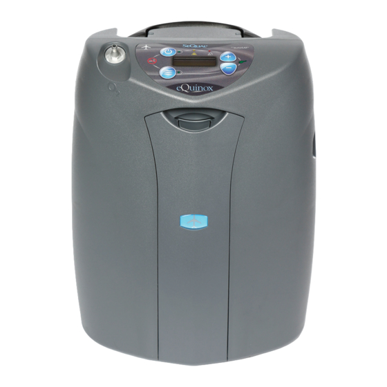
Personal Ambulatory Oxygen System Provider Technical Manual Introduction to the eQuinox Oxygen System eQuinox FRONT Oxygen Outlet Port Handle Control Panel External Power Receptacle Battery Approval Icon Pack Latch Rating Label & Serial Number AC Power Supply eQuinox Cart Location Battery Pack BACK... -
Page 5: Equinox Oxygen System Specifications
Personal Ambulatory Oxygen System Provider Technical Manual eQuinox Oxygen System Specifications 13.6 x 10.6 x 7.4 (inches) Dimensions (H x W X D) (34.5 x 26.9 x 18.8 cm) Weight 12.2 lbs (5.53 kg) unit only eQuinox 14.0 lb (6.35 kg) w/ 12-cell battery installed 12 Cell Battery Pack - 1.85 lbs (0.84 kg) Battery Pack 24 Cell Battery Pack - 3.6 lbs (1.63 kg) -
Page 6: Pulse Dose Mode Specifications
Personal Ambulatory Oxygen System Provider Technical Manual Pulse Dose Mode Specifications Pulse Settings 1.0 to 6.0, in 8mL increments up to 96 mL; 7-9 in 32mL increments up to 192 mL Trigger Sensitivity Adjustable between settings of 1 (most sensitive) to 3 (least sensitive) Adjustable Bolus Rise Time Adjustable settings of Fast(factory setting), Medium, or Slow •... -
Page 7: Compressor And Compressor Enclosure
Personal Ambulatory Oxygen System Provider Technical Manual Compressor and Compressor Enclosure Continuous Flow Mode The eQuinox Compressor is a two-cylinder, variable speed compressor, Continuous Flow Mode delivers a constant flow of oxygen to a patient driven by a highly efficient Brushless DC (BLDC) motor. When air by means of tubing and a nasal cannula at rates between 0.5 LPM and flows into the Compressor enclosure, it passes through an air intake 3.0 LPM. -
Page 8: Service Mode Functions
EDAT EDAT is the world’s first computer-based data retrieval service tool for oxygen concentrators. EDAT is proprietary to CAIRE Inc., and is comprised of both hardware and software components. EDAT is SeQual’s global solution for your service and support needs. -
Page 9: Power Supplies
Personal Ambulatory Oxygen System Provider Technical Manual Power Supplies DC Power Cable The DC Power Cable is intended for use with DC accessory outlets, The eQuinox may operate from either the AC Power Supply, DC Power such as those found in motor vehicles. Input voltage required to power Cable or Battery Pack. - Page 10 Personal Ambulatory Oxygen System Provider Technical Manual The Battery Pack (Battery) may be charged in two ways: (a) place the Battery Pack sufficiently cools. Consider removing the Battery Pack to Battery Pack in the eQuinox and connect the eQuinox to AC or DC allow for faster cooling.
-
Page 11: Charging Algorithm
Battery Pack can sit unused for up to 12 months without appreciable stationary power sources. The eQuinox’s Battery Pack, like all lithium self-discharge occurring. Nevertheless, CAIRE recommends a first in, ion batteries, is susceptible to permanent damage from excessive heat. -
Page 12: Introduction
• Software Revision • Battery Pack Status Gauge The eQuinox is shipped from CAIRE at default flow settings of 2 LPM Continuous Flow, 2.0 Pulse Dose, and 2 for Pulse Mode Sensitivity Adjustment and Fast Rise Time. You may adjust these settings to your patient’s prescription when you deliver and set up the device. -
Page 13: Monthly Maintenance-Patient
Personal Ambulatory Oxygen System Provider Technical Manual Monthly Maintenance—Patient Care for the Battery Pack The Battery Pack in the eQuinox requires special care to assure a longer life and the highest level of performance. The SeQual Battery Pack is the only approved Battery Pack recommended for use with the eQuinox. -
Page 14: Annual Maintenance Procedures
Personal Ambulatory Oxygen System Provider Technical Manual Annual Maintenance Procedures The following section lists procedures that are necessary to maintain the eQuinox. Service should only be performed by a qualified technician. To perform periodic maintenance, the only tools that should be necessary are: •... - Page 15 Personal Ambulatory Oxygen System Provider Technical Manual 4. Once the old battery is removed, insert the new 9-Volt battery by following steps 1-3 in reverse. The polarity of the 9-Volt battery does not have to be Note: aligned in a certain manner when inserting the new 9-Volt battery.
- Page 16 Personal Ambulatory Oxygen System Provider Technical Manual 10. Slide a 3/8”or 10mm deep well socket over the aluminum removed, remove the HEPA filter from the oxygen outlet by un- oxygen outlet, ensuring that the socket makes contact with the screwing the HEPA filter from the oxygen outlet. fitting on the boom of the oxygen outlet.
-
Page 17: Assembly And Alarm Verification Tests
5. If the AC Power Supply measures leakage current greater than the Pack Status Gauge is moving in waterfall fashion (scrolling from criteria in step 3, please return it to CAIRE for service. bottom to top). If the Battery Pack Status Gauge is not moving, 6. -
Page 18: Provider Service And Maintenance Record
Personal Ambulatory Oxygen System Provider Technical Manual Provider Service and Maintenance Record Whenever maintenance or service is performed on an eQuinox unit, an entry should be made in the service log for that concentrator or recorded in accordance with your company’s standard procedure. Whenever the case of the eQuinox is opened, the flow rate, purity, and alarm status should be verified per the Test Procedures in this manual. -
Page 19: Voice Module Operation
Personal Ambulatory Oxygen System Provider Technical Manual Voice Module Operation Increase/Decrease the Volume of Vocal Notifications Voice Module Operational Instructions 1. To increase or decrease the volume of vocal notifications, press the No Smoking Icon & Hidden Key twice. The eQuinox is equipped with the capability of providing vocal 2. -
Page 20: Equinox Voice Message Alert Descriptions Table
Personal Ambulatory Oxygen System Provider Technical Manual eQuinox Voice Message Alert Descriptions Table eQuinox Voice Message Alert Descriptions Condition Standard eQuinox Voice Message Message Repeat Interval Flow rate error > +/- 10% “Low output flow. Check the cannula. ” Continuous until condition is removed. 30 minutes runtime remaining on battery “30 minutes remaining on battery. -
Page 21: Troubleshooting, Service, And Repair Procedures
Personal Ambulatory Oxygen System Provider Technical Manual Troubleshooting, Service, and Repair Procedures CAUTION The eQuinox contains electrostatic sensitive components. Do not open or handle except at a static free workstation. Do not remove cover without ESD protection. To adequately troubleshoot and repair the product Note: in the field, EDAT is recommended. -
Page 22: Alarm Conditions And Alarm Codes
Personal Ambulatory Oxygen System Provider Technical Manual Alarm Conditions and Alarm Codes Use the table below to decode eQuinox alarm conditions. If other alarm codes are displayed by the eQuinox, contact Technical Support for assistance. Note: The following table is intended as a guide for the provider, not the user. Alarm Alarm Green... -
Page 23: Malfunction Codes
Personal Ambulatory Oxygen System Provider Technical Manual Malfunction Codes If a malfunction occurs in the eQuinox, the device will stop, the Red LED on the front panel will light and the buzzer will sound for 10 seconds and then silence. The LCD will display one of the following Malfunction Codes: Malfunction FAIL code Recommended Action... - Page 24 Personal Ambulatory Oxygen System Provider Technical Manual Proportional Valve Control Board Product Tank Intake Port Compressor Assembly Figure 22: eQuinox Internal Components 20771733 D 24...
-
Page 25: Servicing The Equinox
Personal Ambulatory Oxygen System Provider Technical Manual Servicing the eQuinox sliding the top of the back cover over the top of the unit as pictured below. Prior to performing the following procedures, ESD Note: protection must be ensured. Do not touch exposed circuits during maintenance without ESD protection. -
Page 26: Removing/Replacing The Handle And Speaker
Personal Ambulatory Oxygen System Provider Technical Manual II. Removing/Replacing the Handle and 5. Flip the top handle housing over and pull up on the handle to remove/replace. Speaker 1. To remove the speaker, after performing the “Removing/Replacing the Back Cover” section, loosen the four allen-head screws securing the speaker to the back cover. -
Page 27: Removing/Replacing The Compressor Assembly
Personal Ambulatory Oxygen System Provider Technical Manual Removing/Replacing the Compressor Assembly 1. Remove the Top Exhaust Port by gently pulling upward. Figure 33 4. Remove the Intake muffler from the foam section. 5. Gently lift up the foam section, while feeding the protruding wires through the foam, and remove. - Page 28 Personal Ambulatory Oxygen System Provider Technical Manual 4. Remove the aluminum intake tube from the black rubber elbow. Figure 40 6. The Compressor Assembly can now be removed/replaced. To replace the Compressor Assembly, repeat steps 1-5 in reverse order. When installing the new Compressor Assembly, prior to attaching the blue tubing to connect to the ATF, use a cotton swab saturated with Isopropyl Alcohol Note:...
-
Page 29: Removing/Replacing The Atf
Personal Ambulatory Oxygen System Provider Technical Manual V. Removing/Replacing the ATF 3. Using a pair of small cutters, snip the end of the tie-wrap on the soft tubing that connects the ATF to the Product Tank and discard 1. To replace the ATF, Using a small utility knife, cut the two blue the tie-wrap. -
Page 30: Removing/Replacing The Product Tank
Personal Ambulatory Oxygen System Provider Technical Manual VI. Removing/Replacing the Product 3. Using a pair of small cutters, snip the end of the tie-wrap on the bottom of the clear rubber elbow that connects the Product Tank Tank to the aluminum tubing going to the flow tube on the Control Board. -
Page 31: Removing/Replacing The Proportional Flow Valve
Personal Ambulatory Oxygen System Provider Technical Manual VII. Removing/Replacing the 3. Disconnect the Proportional Valve electrical connector from the control board. Proportional Flow Valve 1. Using a pair of small cutters, snip the end of the tie-wrap on the soft tubing connecting the Proportional Valve to the Oxygen Outlet/HEPA Filter housing and gently pull on the tubing to disconnect the tubing from the barb fitting. -
Page 32: Removing/Replacing The Top Cover Foam Section
Personal Ambulatory Oxygen System Provider Technical Manual IX. Removing/Replacing the Top Cover Foam Section 1. Carefully lift the Top Cover Foam Section upward at different locations around the unit, ensuring that all harness wires, cables and tubing are not damaged. This may require tilting, adjusting, turning, etc., the Top Cover Foam section to free from the unit. -
Page 33: Removing/Replacing The Control Board, Power Manager Board, Voice System Board, Battery Bridge Board, Membrane Panel And Wire Harness Assemblies
Personal Ambulatory Oxygen System Provider Technical Manual X. Removing/Replacing the Control Board, Power Manager Board, Voice System Board, Battery Bridge Board, Membrane Panel and Wire Harness Assemblies 1. Once the Top Cover Foam Section has been removed, the Control Board, Power Manager Board, and Wire Harness Assemblies are now ac- cessible. - Page 34 Personal Ambulatory Oxygen System Provider Technical Manual 2. To remove the Power Manager Board, the first step is to cut the tie-wraps that are attaching the two Service Port Wire Harnesses and 9-Volt Wire Harness to the Power Manager Board. Using a pair of small cutters, snip the end of the two tie-wraps. Figure 58 Figure 59 3.
- Page 35 Personal Ambulatory Oxygen System Provider Technical Manual 4. Once the Wire Harnesses have been disconnected, the next step is 7. To remove the Control Board, the first step is to disconnect the loosen the two sets of Jumper Wires that attach from the Battery soft tubing that is connected to the Oxygen Outlet/HEPA Filter Bridge Board to the Power Manager Board.
- Page 36 Personal Ambulatory Oxygen System Provider Technical Manual 9. Next, Disconnect the Power Manager Board/Control Board/Battery FIGURE XX Bridge Board Wire Harness from the Control Board by gently 12. The Control Panel can now be removed by gently lifting upward pulling the connector from the Control Board. on the Control Board.
- Page 37 Personal Ambulatory Oxygen System Provider Technical Manual 23. Place the Battery Bridge Board Installation Fixture into the front Anytime that the Membrane Panel is removed, it must Note: cover, just as if a battery pack was being installed. be replaced with a new Membrane Panel. 19.
- Page 38 Personal Ambulatory Oxygen System Provider Technical Manual Figure 72 Figure 73 28. Remove the four Phillips Head screws that are used to attach the Voice System Board to the Front Cover. Figure 74 29. Once the four screws are removed, the Voice System Board can be removed by gently lifting upward on the Voice System Board.
-
Page 39: Parts List
Personal Ambulatory Oxygen System Provider Technical Manual Parts List Contact Customer Service or visit www.cairemedical.com to obtain your parts list. 20771733 D 39... -
Page 40: Optional Accessories
Visit us at www.CAIREmedical.com for more information about optional accessories. There are many different types of oxygen tubing, cannula, and humidifiers. The following items are recommended by CAIRE Inc. for use with the eQuinox. Salter Labs® Humidifier, Part Number HU003-1, or equivalent: If your physician has prescribed an optional humidifier, follow the manufacturer’s instructions for use. -
Page 41: Caire Inc. Customer Service Contact Information
Loctite® is a registered trademark of Loctite Corporation, USA. Copyright © 2019 CAIRE Inc. CAIRE Inc. reserves the right to discontinue its products, or change the prices, materials, equipment, quality, descriptions, specifications and/or processes to its products at any time without prior notice and with no further obligation or consequence.
Need help?
Do you have a question about the eQuinox PAOS 4000 and is the answer not in the manual?
Questions and answers