Sign In
Upload
Download
Table of Contents
Contents
Add to my manuals
Delete from my manuals
Share
URL of this page:
HTML Link:
Bookmark this page
Add
Manual will be automatically added to "My Manuals"
Print this page
×
Bookmark added
×
Added to my manuals
Manuals
Brands
CAIRE Manuals
Oxygen Equipment
COMPANION 1000
Technical manual
CAIRE COMPANION 1000 Technical Manual
Liquid oxygen portables
Hide thumbs
1
2
3
4
5
6
Table Of Contents
7
8
9
10
11
12
13
14
15
16
17
18
19
20
21
22
23
24
25
26
27
28
29
30
31
32
33
34
35
36
37
38
39
40
41
42
43
44
45
46
47
48
49
50
51
52
53
54
55
56
57
58
59
60
61
62
63
64
65
66
67
68
69
70
71
72
73
74
75
76
77
78
79
80
81
82
83
84
85
86
page
of
86
Go
/
86
Contents
Table of Contents
Troubleshooting
Bookmarks
Table of Contents
Table of Contents
Section 1: Introduction
Product Description
Serial Number Identification
Safety Precautions
Cold Safety
Expansion Safety
Fire Safety
Companion 1000/T Specifications
Table 1-1: Performance Specifications
Unpacking, Installation, and Repacking
Installation
Table 1-2: Run Time Specifications
Unpacking
Repackaging for Return
Controls, Indicators, and Connectors
Fill Connector
Vent Valve
Contents Indicator
Flow Control
Oxygen Outlet Connector
Moisture Cup Assembly (Companion T)
Filling Instructions for Technicians
Pre-Fill Inspection
Filling Procedure
Post-Fill Inspection
Operating Procedure
Maintenance
Recommended Tools, Test Equipment, and Service Materials
Calibrating Test Equipment
Accessories
Section 2: Theory of Operation
Companion 1000/T Component Descriptions
Cryogenic Container
Fill Connector
Warming Coil
Flow Control Valve
Vent Valve
Primary/Secondary Relief Valve
Contents Indicator Scale
Liquid Oxygen Saturation Principles
Companion 1000/T Operation
Filling
Fill Termination
Standby
Oxygen Flow
Section 3: Performance Verification
Equipment Required
Leakage Test
Liquid Leak Detector Test
Pressure Hold Test
Gaseous Oxygen Tests
Secondary Relief Valve Test
Primary Relief Valve Test
Vent Valve Test
Liquid Oxygen Tests
Contents Indicator Test
Flow Control Test
Normal Evaporation Rate Test
Section 4: Troubleshooting
Section 5: Service and Repair
Pressure Fittings and Connections
Compression Fitting Makeup
Compression Fitting Remake
Compression Fitting Troubleshooting
Tapered Pipe Thread Makeup
Tapered Pipe Thread Troubleshooting
Side Covers
Removal
Service
Installation
Top Bezel
Removal
Carrying Strap
Service
Installation
Contents Indicator
Removal
Disassembly
Inspection
Reassembly
Installation
Flow Control Valve
Removal
Backflushing
Repair
Installation
Primary Relief Valve
Removal
Installation
Secondary Relief Valve
Removal
Vent Valve
Adjustment
Installation
Female Fill Connector
Removal
Disassembly
Inspection
Service
Reassembly
Installation
Warming Coil (Companion 1000)
Removal
Warming Coil (Companion T)
Warming Coil Part 1 Removal
Installation
Warming Coil Part 1 Installation
Warming Coil Part 2 Removal
Warming Coil Part 2 Installation
Spined Tube Removal
Spined Tube Installation
Manifold
Removal
Installation
Cryogenic Container
Removal
Installation
Returning the Unit for Service
Section 6: Parts Lists and Illustrations
Advertisement
Quick Links
1
Companion 1000/T Specifications
2
Controls, Indicators, and Connectors
3
Filling Procedure
4
Maintenance
Download this manual
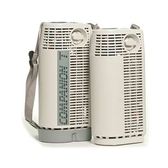
COMPANION 1000
CAIRE Inc.
COMPANION T
L I Q U I D
O X Y G E N
P O R T A B L E S
TECHNICAL MANUAL
CAIRE Inc.
Part Number B-701964-00 Rev. C
Table of
Contents
Previous
Page
Next
Page
1
2
3
4
5
Advertisement
Table of Contents
Troubleshooting
SECTION 4: TROUBLESHOOTING
47
Compression Fitting Remake
51
Tapered Pipe Thread Troubleshooting
52
Need help?
Do you have a question about the COMPANION 1000 and is the answer not in the manual?
Ask a question
Questions and answers
Related Manuals for CAIRE COMPANION 1000
Oxygen Equipment CAIRE COMPANION T Technical Manual
Liquid oxygen portables (86 pages)
Oxygen Equipment CAIRE Companion 5 User Manual
Oxygen concentrator (16 pages)
Oxygen Equipment CAIRE Companion 5 Provider Technical Manual
Oxygen concentrator (38 pages)
Oxygen Equipment CAIRE Companion Series User Manual
Liquid oxygen systems (30 pages)
Oxygen Equipment CAIRE FreeStyle Comfort User Manual
(33 pages)
Oxygen Equipment CAIRE HELiOS Marathon H850 Use Manual
Portable oxygen unit (58 pages)
Oxygen Equipment CAIRE FreeStyle Comfort User Manual
Portable oxygen concentrator with autosat, ultrasense and autodose (546 pages)
Oxygen Equipment CAIRE FreeStyle Comfort Technical Manual
(33 pages)
Oxygen Equipment CAIRE AirSep VisionAire 5 Quick Reference Manual
Compact stationary oxygen concentrators (2 pages)
Oxygen Equipment Caire FreeStyle Quick Reference Manual
Portable oxygen concentrators (2 pages)
Oxygen Equipment CAIRE FreeStyle Manual
Portable oxygen concentrators with ultrasense and patient-removable (91 pages)
Oxygen Equipment CAIRE VisionAire 5 Technical & Service Manual
(45 pages)
Oxygen Equipment CAIRE VisionAire 5 User Manual
(25 pages)
Oxygen Equipment CAIRE FreeStyle Comfort User Manual
Portable oxygen concentrator with autosat, ultrasense and autodose (500 pages)
Oxygen Equipment CAIRE eQuinox PAOS 4000 Provider Technical Manual
Personal ambulatory oxygen system (paos) (41 pages)
Oxygen Equipment CAIRE HI Flow Operating Instructions Manual
(19 pages)
This manual is also suitable for:
Companion t
Table of Contents
Save PDF
Print
Rename the bookmark
Delete bookmark?
Delete from my manuals?
Login
Sign In
OR
Sign in with Facebook
Sign in with Google
Upload manual
Upload from disk
Upload from URL


Need help?
Do you have a question about the COMPANION 1000 and is the answer not in the manual?
Questions and answers