
Related Manuals for SEA USER 1 24V DG MAXI


Summary of Contents for SEA USER 1 24V DG MAXI
- Page 1 International registered trademark n. 804888 USER 1 24V DG MAXI S.p.A. ona Ind striale Sant Atto eramo I A elephone .seateam.com seacom seateam.com 4112 1 REV. 4 2/2 1...
-
Page 2: Description Of The Components
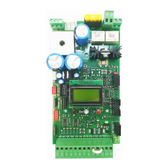
English DESCRIPTION OF THE COMPONENTS TECHNICAL SPECIFICATIONS Control unit power supply: 24 V~ Maximum motor current: 20A Absorption in stand by: 30 mA Environment temperature: -20°C +50°C Specifications of external enclosure: 305 x 225 x 125 mm - Ip55 MOTOR LIGHT FUSE POWER - S +... - Page 3 English CONNECTIONS POWER (CN8) MOTOR (CN6) LIGHT (CN5) 24V (Red) Brown Limit switch Cl.1 (Yellow) White Limit switch Op.1 (Green) Green Common (White) Max 400W Max 100mA 24V~ Limit switch Cl.1 (Yellow) Limit switch Op.1 (Green) LIGHT (CN5) 9 10 11 12 13 ANT COM START PEDST STOP COM PH1 PH2 EDGE AUX COM 24V (FL)-...
- Page 4 English QUICK SELF-EARNING PROGRAMMING “Input check DISPLAY menu" -- --- DOWN DOWN Fast self-learning START command by Start quick programming radio control You can start the quick programming by You can store the START button of the holding UP for 5 s in the “Input check remote control while pressing DOWN for 5 s menu", until the motor starts.
-
Page 5: Programming Quick Start
English PROGRAMMING QUICK START PROGRAMMING BUTTONS MENU MENU LANGUAGE ITALIANO DOWN Skip this step if you do not want to program a transmitter OK to exit Press the Menu or press MENU MENU MENU MENU button of the the button of PRESS TX to be START... - Page 6 English WORKING TIMES SELF-LEARNING WORKING TIME SELF-LEARNING ON MOTORS WITH LIMIT-SWITCH PRELIMINARY NOTE: When using magnetic limit switches (such as on B-200 model), make sure that the control unit is set on «magnetic limit switch» before learning: MENU 104 - SELECT LIMIT SWITCH - “Magnetic” 1) Turn off the power supply, release the motor and place the door (or the barrier) manually at its mid run Reset the mechanical lock Select 9 - PROGRAMMING on the display, press OK and then one of the UP or DOWN buttons.
-
Page 7: Function Logic
If the password has been forgotten, the only way to unlock the control unit is to contact the SEA technical assistance, which will assess whether to provide the procedure to unlock the control unit or not. - Page 8 USER 1 24V DG MAXI MENU FUNCTIONS TABLE DEFAUL MENU DESCRIPTION VALUE Italiano Italian English English 1 LANGUAGE Français French English Español Spanish Dutch Dutch Start Start Partial opening Partial opening External module External module Stop Stop Start Pressed once, it stops the gate. Pressed twice,...
-
Page 9: Special Menu
PRESS AT THE SAME TIME FOR 5 SECONDS TO ENTER OR TO EXIT THE SPECIAL MENU DO W N SPECIAL MENU FUNCTIONS TABLE USER 1 24V DG MAXI For entering into the special menu move on one of the menu and press the UP and DOWN buttons at the same time for 5 seconds... - Page 10 DEFAUL MENU DESCRIPTION VALUE Shows the absorbed current by the motor during the movement. The letter H at the 57 WORKING CURRENT 1 _ _ _ _ _ left of the current value indicates the exceeding of the set inversion threshold 59 OPENING SLOWDOWN 1 Off (*) From OFF to 50% of the stroke...
- Page 11 DEFAUL MENU DESCRIPTION VALUE Always AUX output always Power supplied In cycle AUX output active only during cycle Opening AUX power supplied only during opening Closing AUX power supplied only during closing In pause AUX power supplied only during pause Fototest Security test AUX output only during cycle with fototest...
- Page 12 DEFAUL MENU DESCRIPTION VALUE If the photocell is occupied, it reverses the Closing movement in closing; during the pause, it prevents the reclosing The photocell blocks the movement as long as Opening and closing it is occupied; when released, the opening movement continues If the photocell is occupied before the Start input, the Start will be ignored.
- Page 13 DEFAUL MENU DESCRIPTION VALUE On applications with two motors in master- Master slave, it allows to set the control unit as master 105 MASTER-SLAVE On applications with two motors in master- Slave slave, it allows to set the control unit as slave Disabled 106 DIAGNOSTICS Shows last event (See alarms table)
- Page 14 JOINT Photocell 1 Edge 1 DOWN Photocell 2 MENU FUNCTION TABLE CHECK USER 1 24V DG MAXI INPUTS To access the Menu for input check keep pressed OK for about 5 seconds. Description MENU Description The contact must be a N.O. Contact . When activating the related...
- Page 15 English RADIO TRANSMITTER SELF LEARNING WITH RECEIVER ON BOARD OF CONTROL UNIT WARNING: Make the radio transmitters programming before you connect the antenna and insert the receiver into the special CMR connector (if available) with turned off control unit. With RF UNI and RF UNI PG module it will be possible to use both Coccinella Roll Plus transmitters and radio transmitters with fixed code.
- Page 16 English RADIO TRANSMITTER SELF LEARNING WITH RF FIX RECEIVER ON BOARD OF CONTROL UNIT WARNING: Make the radio transmitters programming before you connect the antenna and insert the receiver into the special CNS connector (if available) with turned off control unit. With the RF FIX module it will be possible to use only radio controls with fixed code.
- Page 17 n lis START - STOP - PEDESTRIAN START - ANTENNA - PHOTOCELL hotocell 1 and hotocell 2 onnections + 24 (Accessories) max 750mA COM 0 PH1 Photocell contact 1 PH2 Photocell contact 2 ote: Self-test: connect the T to the AU clamp and activate the Autotest function. The photocell 1 default setting is FOTO CLOSE and the photocell 2 one is FOTO OPEN.
- Page 18 English WARNING LAMP - SAFETY EDGE - 10K PHOTOCELL - BUZZER FLASHING LAMP 3W MAX 12 and 13 Flashing Lamp 24V (Accessories) 3W Max (Control lamp) The Flashing Lamp can be connected between the 24V clamps 9 10 11 12 13 (Accessories) and FL (-) of CN1.
- Page 19 n lis SAFETY LOOP CONNECTIONS DRA I G S MAG E I 1 11 12 1 C C2 Safet e it loop loop 1 24 V Connecting scheme of loop detector 1 reader Contact photocell 1 (N.C.) Common Shado loop loop 2 Connecting scheme of loop detector 2 reader Contact photocell 2 (N.C.)
-
Page 20: Connection Of Batteries
n lis CONNECTION OF BATTERIES TO BATTERY CHARGER CARD E SU E SU ode 2 1 11 ode 2 1 11 4 = charge 200mA = charge 200mA = charge 360mA = charge 360mA = charge 800mA = charge 800mA PSOL GND S 28V GND PSOL BAT 28V... -
Page 21: Master-Slave Function
2) Once sure of the correct functioning connect the control unit MASTER to the control unit SLAVE through the special clamp (Code SEA 23001220). 3) Now set the control unit, which has to manage the commands and motor 1 (photocell, keyswitch, STOP, safety edge etc.) as MASTER and the other one which will move motor 2 as SLAVE. -
Page 22: Motor Power Supply
The first movement in selflearning must alwa s be executed in closing. ATTENTION: hen using SEA magnetic limit switches, ma e sure that 9 10 11 12 13 the motor is set on Magnetic present in the special menu 104-SELECT... - Page 23 English TRAFFIC LIGHT CARD CONNECTION 24V~ / (ac/dc) 230V~ 1 CNP Connect on EXP terminal COURTESY LIGHT OUTPUT 24V/DRY CONTACT MANAGEMENT 1 2 3 With JP1 off and JP2 inserted between 1 and 2 of CN5 you will have a clean contact that is activated based on the setting given by the menu 88 (one second from each start pulse, only during cycle or for the set time) With JP1 inserted and JP2 inserted between 2 and 3 of CN5...
-
Page 24: Alarm Description
English ALARM DESCRIPTION Solutions Signals Kind of alarm Be sure there are no short circuits on the motor or on the control unit; Check that the gate is not locked or stuck in stop; Check that the FAILURE BLOCKED encoder (if active) is connected to the control unit; By unlocking the MOTOR Motors current gate, try giving a start and hear if the motor runs dry;... -
Page 25: Troubleshooting
English TROUBLESHOOTING Advices Make sure all Safeties are turned ON Problem Found Possible Cause Solutions a) Check the connections or the jumpers on the connections of Operator doesn’t respond to a) Check the connected N.C. contacts the safety edge or of the stop and of the photocell if connected any START impulse b) Burnt fuse b) Replace the burnt fuse on the control unit... - Page 26 English Advices Make sure all Safeties are turned ON Problem Found Possible Cause Solutions a) Check all Open inputs for an active input a) Open control active b) Check pause settings Gate opens, but will not close b) Pause not set c) Check all Entrapment Protection Device inputs for an active with transmitter or pause time c) Close Entrapment Protecting Device active...
- Page 27 Materials handling must be made with appropriate vehicles.. WARRANTY LIMITS For the guarantee see the sales conditions on the official SEA price list. SEA reserves the right to make any required modification or change to the products and/or to this manual without any advanced notice obligation.
- Page 28 Transport of the goods sold shall be at Bu er s cost and ris . SEA shall not bear the costs of deliver giving the goods to the carrier, as chosen either b SEA or b the Bu er. An loss and/or damage of the goods during transport, are at Bu er s cost.
- Page 29 5. Do not install the equipment in an explosive atmosphere. 6. SEA S.p.A. is not responsible for failure to observe ood Techniques in the construction of the loc ing elements to motorize, or for an deformation that ma occur during use.
- Page 30 La SEA S.p.A. dichiara sotto la propria responsabilità e, se applicabile, del suo rappresentante autorizzatoche il prodotto: SEA S.p.A. declares under its proper responsability and, if applicable, under the responsability of its authorised representative that the product: Descrizione / Description...
- Page 31 Cet article a t produit suivant des proc dures d usinage strictes et il a singulièrement t test afin de garantir les plus hauts niveaux de qualit pour votre satisfaction. Nous vous remercions d avoir choisi SEA. Este articulo ha sido producido siguiendo rigidos procedimientos de elaboracion...
- Page 32 International registered trademark n. 804888 SEA S.p.A. ona ind striale 4 2 S.A eramo 41 r.a. a .seateam.com seacom seateam.com...
Need help?
Do you have a question about the USER 1 24V DG MAXI and is the answer not in the manual?
Questions and answers