SEA USER 1 - 24V DG MAXI Manual
Electronic control unit for sliding gates and barriers
Hide thumbs
Also See for USER 1 - 24V DG MAXI:
Advertisement
Quick Links
Download this manual
See also:
Manual
®
English
Sistemi Elettronici
di Apertura Porte e Cancelli
International registered trademark n. 804888
USER 1 - 24V DG MAXI
23024074
24V
ELECTRONIC CONTROL UNIT FOR SLIDING GATES AND BARRIERS
SEA S.p.A.
Zona Ind.le S. Atto - 64020 S. Nicolò a Tordino (TE)
Tel. 0861.588341 - Fax 0861.588344
www.seateam.com
e-mail: seacom@seateam.com
67411261
REV. 02 - 01/2017
Advertisement

Related Manuals for SEA USER 1 - 24V DG MAXI


Summary of Contents for SEA USER 1 - 24V DG MAXI
- Page 1 English Sistemi Elettronici di Apertura Porte e Cancelli International registered trademark n. 804888 USER 1 - 24V DG MAXI 23024074 ELECTRONIC CONTROL UNIT FOR SLIDING GATES AND BARRIERS SEA S.p.A. Zona Ind.le S. Atto - 64020 S. Nicolò a Tordino (TE) Tel.
-
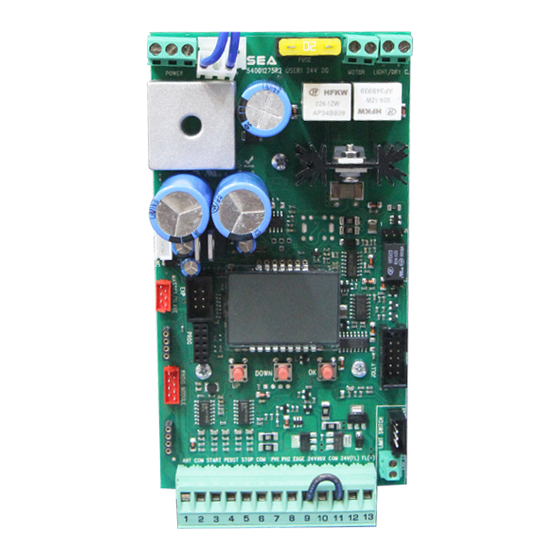
Page 2: Description Of The Components
English DESCRIPTION OF THE COMPONENTS TECHNICAL SPECIFICATIONS Control unit power supply: 24 V~ Absorption in stand by: 30 mA Maximum motor current: 20A Environment temperature: -20°C +50°C Specifications of external enclosure: 305 x 225 x 125 mm - Ip55 MOTOR LIGHT FUSE POWER - S +... - Page 3 English CONNECTIONS POWER (CN8) MOTOR (CN6) LIGHT (CN5) 24V (Red) Brown Limit switch Cl.1 (Yellow) White Limit switch Op.1 (Green) Green Common (White) Max 400W Max 100mA 24V~ Limit switch Cl.1 (Yellow) Limit switch Op.1 (Green) LIGHT (CN5) 9 10 11 12 13 ANT COM START PEDST STOP COM PH1 PH2 EDGE AUX COM 24V (FL)-...
- Page 4 English QUICK SELF-EARNING PROGRAMMING “Input check DISPLAY menu" -- --- DOWN DOWN Fast self-learning START command by Start quick programming radio control You can start the quick programming by You can store the START button of the holding UP for 5 s in the “Input check remote control while pressing DOWN for 5 s menu", until the motor starts.
-
Page 5: Quick Start
English PROGRAMMING QUICK START PROGRAMMING BUTTONS MENU MENU LANGUAGE ITALIANO DOWN Skip this step if you do not want to program a transmitter OK to exit Press the Menu or press MENU MENU MENU MENU button of the PRESS the button of TRANSMITTERS STORED START... - Page 6 English MENU FUNCTIONS TABLE USER1 24V DG MAXI MENU Description Default Set value Italiano Italian English English 1 - LANGUAGE Italiano French Français Spanish Español Olandese Dutch Start Start Pedestrian Start Pedestrian Start External module External module Start Stop Stop 2 - TRANSMITTERS Pedestrian Storing of a command for...
-
Page 7: Function Logic
English WORKING TIMES SELF LEARNING NOTE: When using a magnetic limit switches in general; make sure that the control unit is set on magnetic limit switch before learning. MENU 104 - SELECT LIMIT SWITCH - “Magnetic” 1) Disconnect the power supply, release the motor (Fig. 1) and manually position the leaves or the beam on halfway (Fig. 3-4). 2) Reset the mechanical lock (Fig. - Page 8 English SPECIAL MENU PRESS AT THE SAME TIME FOR 5 SECONDS TO ENTER OR TO EXIT THE SPECIAL MENU DOWN SPECIAL MENU FUNCTIONS TABLE USER 1 24V DG MAXI For entering into the special menu move on one of the menu and press the UP and DOWN buttons at the same time for 5 s.
- Page 9 English MENU SP Description Default Set Value Disabled 59 - OPENING * 30 SLOWDOWN 1 * Setting from 5 to 100 Disabled 60 - CLOSING * 30 SLOWDOWN 1 * Setting from 5 to 100 Adjust the passage between normal speed 63 - DECELERATION 100% and slowdown speed...
- Page 10 English MENU SP Description Default Set Value With J1 between 2 and 3, and J2 inserted on CN5, you will 1 240 have 24 volts only during the cycle plus for the set time. With J1 between 2 and 3, and J2 inserted on CN5, you will In cycle have 24V only during the cycle.
- Page 11 English MENU SP Description Default Set Value Auto-test active only on Photo1 Photo1 Auto-test active only on 95 - FOTOTEST Photo1-2 Photo2 Photo2 Auto-test active on Photo1-2 Photo1 and Photo2 Closing Photocell active in closing Active in opening Opening and closing and closing Photocell active before Stop...
- Page 12 English MENU SP Description Default Set Value For applications with two motors in master-slave, it Master allows to set the control unit as master For applications with two 105 - MASTER-SLAVE motors in master-slave, Slave you can set the control unit as slave Disabled Shows last event...
- Page 13 English INPUT CHECK MENU The settings of the control unit are made through the UP, DOWN and OK buttons. The UP and DOWN buttons to scroll through the MENUS and SUBMENUS. By pressing OK you enter from MENU into SUBMENU and confirm the choice. Moving in the 1-LANGUAGE menu pressing the UP and DOWN buttons at the same time you access the SP MENU for special settings.
- Page 14 English RADIO TRANSMITTER SELF LEARNING WITH RECEIVER ON BOARD OF CONTROL UNIT WARNING: Make the radio transmitters programming before you connect the antenna and insert the receiver into the special CMR connector (if available) with turned off control unit. With RF UNI and RF UNI PG module it will be possible to use both Coccinella Roll Plus transmitters and radio transmitters with fixed code.
- Page 15 English RADIO TRANSMITTER SELF LEARNING WITH RF FIX RECEIVER ON BOARD OF CONTROL UNIT WARNING: Make the radio transmitters programming before you connect the antenna and insert the receiver into the special CNS connector (if available) with turned off control unit. With the RF FIX module it will be possible to use only radio controls with fixed code.
- Page 16 English START - STOP - PEDESTRIAN START - ANTENNA - PHOTOCELL Photocell 1 and Photocell 2 Connections + = 24V (Accessories) max 750mA COM = 0V PH1 = Photocell contact 1 PH2 = Photocell contact 2 1 2 3 4 5 6 7 8 Note: For the autotest connect the TX to the AUX clamp and activate the Autotest function.
- Page 17 The first movement in selflearning must always be executed in closing. ATTENTION: When using SEA magnetic limit switches, make sure that the motor is set on 9 10 11 12 13 “Magnetic”...
-
Page 18: Motor Power Supply
English MOTOR POWER SUPPLY TRANSFORMER 115V~ 230V~ 3,6A blow fuse on 230V ~ power supply 6,3A blow fuse on 115V ~ power supply POWER (CN8) Power input Input for the connection of the electric power. P = PHASE NOTICE: for the N = NEUTRAL connection to the MOTOR... - Page 19 English WARNING LAMP - SAFETY EDGE - 10K PHOTOCELL - BUZZER Example of a Flashing Lamp FLASHING LAMP 3W MAX 12 and 13 and an Edge connections Flashing Lamp 24V (Accessories) 3W max. (Control lamp) The Flashing Lamp can be connected between the 24V clamps (Accessories) and FL (-) of CN 1.
- Page 20 English SAFETY LOOP CONNECTIONS DRAWING SHOWS HOW TO EVENTUALLY CONNECT THE MAGNETIC LOOP 1 2 3 4 5 6 7 8 9 10 11 12 13 C2 C2 C1 = CONTACT OPEN Safety exit loop (loop 1) C2 = CONTACT CLOSED 12 = 24 V Connecting scheme of C = 0 V...
-
Page 21: Master-Slave Function
2) Once sure of the correct functioning connect the control unit MASTER to the control unit SLAVE through the special clamp (Code SEA 23001220). 3) Now set the control unit, which has to manage the commands and motor 1 (photocell, keyswitch, STOP, safety edge etc.) as MASTER and the other one which will move motor 2 as SLAVE. - Page 22 If the password has been forgotten, the only way to unlock the control unit is to contact the SEA technical assistance, which will assess whether to provide the procedure to unlock the control unit or not.
-
Page 23: Troubleshooting
English TROUBLESHOOTING Advices Make sure all Safeties are turned ON Problem Found Possible Cause Solutions a) Check the connections or the jumpers on the connections of Operator doesn’t respond to a) Check the connected N.C. contacts the safety edge or of the stop and of the photocell if connected any START impulse b) Burnt fuse b) Replace the burnt fuse on the control unit... - Page 24 English Advices Make sure all Safeties are turned ON Problem Found Possible Cause Solutions a) Check all Open inputs for an active input a) Open control active b) Check pause settings Gate opens, but will not close b) Pause not set c) Check all Entrapment Protection Device inputs for an active with transmitter or pause time c) Close Entrapment Protecting Device active...
- Page 25 Materials handling must be made with appropriate vehicles.. WARRANTY LIMITS For the guarantee see the sales conditions on the official SEA price list. SEA reserves the right to make any required modification or change to the products and/or to this manual without any advanced notice obligation.
- Page 26 5. Do not install the equipment in an explosive atmosphere. 6. SEA S.p.A. is not responsible for failure to observe Good Techniques in the construction of the locking elements to motorize, or for any deformation that may occur during use.
- Page 27 The recognized defects, whatever their nature, shall not produce any responsibility and/or damage claim on the part of the Buyer against SEA. The guarantee is in no case recognized if changes are made to the goods, or in the case of improper use, or in the case of tampering or improper assembly, or if the label affixed by the manufacturer has been removed including the SEA registered trademark No.
- Page 28 Cet article a été produit suivant des procédures d'usinage strictes et il a singulièrement été testé afin de garantir les plus hauts niveaux de qualité pour votre satisfaction. Nous vous remercions d'avoir choisi SEA. Este articulo ha sido producido siguiendo rigidos procedimientos de elaboracion y ha sido probando singolarmente a fin de garantizar los mas altos inveles de calidad y vuestra satisfaccion.
- Page 29 Dichiarazione di conformità Declaration of Conformity La SEA S.p.A. dichiara sotto la propria responsabilità e, se applicabile, del suo rappresentante autorizzato che il prodotto: SEA S.p.A. declares under its proper responsability and, if applicable, under the responsability of its authorised...
- Page 30 ® Sistemi Elettronici di Apertura Porte e Cancelli International registered trademark n. 804888 Note - Notes - Note - Notas - Anmerkung...
- Page 31 ® Sistemi Elettronici di Apertura Porte e Cancelli International registered trademark n. 804888 Note - Notes - Note - Notas - Anmerkung...
- Page 32 ® Sistemi Elettronici di Apertura Porte e Cancelli International registered trademark n. 804888 SEA S.p.A. Zona industriale 64020 S.ATTO Teramo - (ITALY) Tel. +39 0861 588341 r.a. Fax +39 0861 588344 www.seateam.com seacom@seateam.com...
Need help?
Do you have a question about the USER 1 - 24V DG MAXI and is the answer not in the manual?
Questions and answers