Table of Contents
Advertisement
Quick Links
Download this manual
See also:
Manual
International registered trademark n. 2.777.971
USER 1 - 24V DG R1B
24V
ELECTRONIC CONTROL UNIT FOR SLIDING GATES AND BARRIERS
SEA USA Inc.
10850 N.W. 21st unit 160 DORAL MIAMI
Florida (FL) 33172 USA
Tel.
:++1-305.594.1151 ++1-305.594.7325
-
Toll free:
800.689.4716
web site: www.sea-usa.com
e-mail: sales@sea-usa.com
67411535
REV 08 - 12/2015
Advertisement
Table of Contents

Subscribe to Our Youtube Channel
Related Manuals for SEA USER 1-24V DG R1B


Summary of Contents for SEA USER 1-24V DG R1B
- Page 1 International registered trademark n. 2.777.971 USER 1 - 24V DG R1B ELECTRONIC CONTROL UNIT FOR SLIDING GATES AND BARRIERS SEA USA Inc. 10850 N.W. 21st unit 160 DORAL MIAMI Florida (FL) 33172 USA Tel. :++1-305.594.1151 ++1-305.594.7325 Toll free: 800.689.4716 web site: www.sea-usa.com e-mail: sales@sea-usa.com...
- Page 2 USER 1 - 24V DG R1B International registered trademark n. 2.777.971 Details General An appliance shall be provided with an instruction manual. The instruction manual shall give instructions for the installation, operation, and user maintenance of the appliance. The installation instructions shall specify the need for a grounding-type receptacle for connection to the supply and shall stress the importance of proper grounding.
- Page 3 USER 1 - 24V DG R1B International registered trademark n. 2.777.971 g) The Stop and/or Reset button must be located in the line-of-sight of the gate. Activation of the reset control shall not cause the operator to start. h) A minimum of two (2) WARNING SIGNS shall be installed, one on each side of the gate where easily visible. i) For gate operators utilizing a non-contact sensor: 1) See instructions on the placement of non-contact sensors for each Type of application, 2) Care shall be exercised to reduce the risk of nuisance tripping, such as when a vehicle, trips the sensor while the gate is...
-
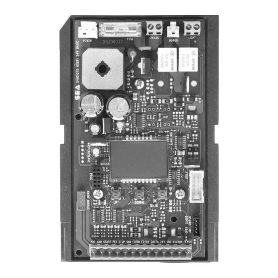
Page 4: Description Of The Components
USER 1 - 24V DG R1B DESCRIPTION OF THE COMPONENTS TECHNICAL SPECIFICATIONS Control unit power supply: 24 V~ Absorption in stand by: 30 mA Environment temperature: -20 (-4°F +122°F) Specifications of external enclosure: 305 x 225 x 125 mm (12 x 9 x 5 inches) - Ip55 LIGHT FUSE POWER... - Page 5 USER 1 - 24V DG R1B CONNECTIONS POWER (CN8) MOTOR (CN6) LIGHT (CN5) 24V (Red) Brown Limit switch Cl.1 (Yellow) White Green Limit switch Op.1 (Green) 24V~ Common (White) Max 200W Max 100mA 9 10 11 12 13 ANT COM START PEDST STOP COM PH1 PH2 EDGE AUX COM 24V (FL)- JUMPERS...
- Page 6 USER 1 - 24V DG R1B PROGRAMMING FAST SELF-LEARNING “I nput check menu " DISPLAY DOWN 1 2 3 4 5 6 7 8 9 10 11 12 13 DOWN Fast self-learning START command by Start quick programming radio control You can start the quick programming by You can store the START button of the holding UP for 5 s in the “I...
- Page 7 USER 1 - 24V DG R1B PROGRAMMING QUICK START PROGRAMMING BUTTONS MENU MENU LANGUAGE ITALIANO DOWN Skip this step if you do not want to program a transmitter OK to exit Press the Menu or press MENU MENU MENU MENU button of the PRESS the button of...
- Page 8 USER 1 - 24V DG R1B MENU FUNCTIONS TABLE USER1 24V DG R1B MENU Description Default Set value Italiano Italian English English 1 - LANGUAGE Italiano Français French Spanish Español Olandese Dutch Start Start Pedestrian Start Pedestrian Start External module External module Start Stop...
-
Page 9: Function Logic
USER 1 - 24V DG R1B WORKING TIMES SELF LEARNING NOTE: When using a B200 motor or magnetic limit switches in general; make sure that the control unit is set on magnetic limit switch before learning. MENU 104 - SELECT LIMIT SWITCH - “Magnetic” 1) Disconnect the power supply, release the motor (Fig. -
Page 10: Special Menu
USER 1 - 24V DG R1B SPECIAL MENU PRESS AT THE SAME TIME FOR 5 SECONDS TO ENTER OR TO EXIT THE SPECIAL MENU DOWN SPECIAL MENU FUNCTIONS TABLE USER 1 24V DG R1B For entering into the special menu move on one of the menu and press the UP and DOWN buttons at the same time for 5 s. - Page 11 USER 1 - 24V DG R1B MENU SP Description Default Set Value Adjust the tolerance between 72 - OPENING TOLERANCE 0 100 stop and obstacle opening MOTOR1 Adjust the tolerance between 73 - CLOSING TOLERANCE 0 100 stop and obstacle closing MOTOR1 Only opening If you force the gate...
- Page 12 USER 1 - 24V DG R1B MENU SP Description Default Set Value AUX output always Always power supplied AUX output active only In cycle during cycle AUX output power Opening supplied only during opening AUX output power Closing supplied only during closing AUX output power In pause supplied only during pause...
- Page 13 USER 1 - 24V DG R1B MENU SP Description Default Set Value Closing Photocell active in closing Active in opening Opening and closing and closing Photocell active before Stop opening The photocell stops in closing Stop and close and closes when released The photocell gives a command to close during 98 - PHOTO2...
- Page 14 USER 1 - 24V DG R1B INPUT CHECK MENU The settings of the control unit are made through the UP, DOWN and OK buttons. The UP and DOWN buttons to scroll through the MENUS and SUBMENUS. By pressing OK you enter from MENU into SUBMENU and confirm the choice. Moving in the 1-LANGUAGE menu pressing the UP and DOWN buttons at the same time you access the SP MENU for special settings.
- Page 15 USER 1 - 24V DG R1B RADIO TRANSMITTER SELF LEARNING WITH RECEIVER ON BOARD OF CONTROL UNIT WARNING: Make the radio transmitters programming before you connect the antenna and insert the receiver into the special CMR connector (if available) with turned off control unit. With RF UNI and RF UNI PG module it will be possible to use both Coccinella Roll Plus transmitters and radio transmitters with fixed code.
- Page 16 USER 1 - 24V DG R1B START - STOP - PEDESTRIAN START - ANTENNA - PHOTOCELL Photocell 1 and Photocell 2 Connections + = 24V (Accessories) max 750mA COM = 0V PH1 = Photocell contact 1 PH2 = Photocell contact 2 Note: For the autotest connect the TX to the AUX clamp and activate the Autotest function.
-
Page 17: Limit Switch
The first Limit Switch movement in selflearning must always be executed in closing. ATTENTION: When using SEA magnetic limit switches, make sure that the motor is set on “Magnetic” present in the special menu 104-SELECT LIMIT SWITCH. ALARMS INDICATIONS Signals... -
Page 18: Motor Power Supply
USER 1 - 24V DG R1B MOTOR POWER SUPPLY TRANSFORMER 115V~ 230V~ 3,6 A blow fuse on 230V ~ power supply 6,3A blow fuse on 115V ~ power supply POWER (CN8) WARNING: K e e p t h e p o w e r c a b l e s ( m o t o r s , p o w e r Power input supply) SEPARATE from the... -
Page 19: Master-Slave Function
2) Once sure of the correct functioning connect the control unit MASTER to the control unit SLAVE through the special clamp (Code SEA 23001220). 3) Now set the control unit, which has to manage the commands and motor 1 (photocell, keyswitch, STOP, safety edge etc.) as MASTER and the other one which will move motor 2 as SLAVE. - Page 20 If the password has been forgotten, the only way to unlock the control unit is to contact the SEA technical assistance, which will assess whether to provide the procedure to unlock the control unit or not.
-
Page 21: Troubleshooting
Materials handling must be made with appropriate vehicles.. WARRANTY LIMITS For the guarantee see the sales conditions on the official SEA price list. SEA reserves the right to make any required modification or change to the products and/or to this manual without any advanced notice obligation. - Page 22 PAYMENT: Method of payments and terms are notified by SEA and displayed on the commercial invoice. DELIVERY: The delivery time on the invoice is not binding and represents an estimated delivery. Shipments costs will be charged to the buyer and SEA is not responsible for delays and/or damages occurred to the products during shipment.
- Page 24 International registered trademark n. 2.777.971 SEA USA Inc. 10850 N.W. 21st unit 160 DORAL MIAMI Florida (FL) 33172 USA Tel. ++1-305.594.1151 ++1-305.594.7325 Toll free: 800.689.4716 web site: www.sea-usa.com e-mail: sales@sea-usa.com...
Need help?
Do you have a question about the USER 1-24V DG R1B and is the answer not in the manual?
Questions and answers