Table of Contents
Advertisement
Advertisement
Table of Contents

Related Manuals for SEA GATE 2


Summary of Contents for SEA GATE 2
- Page 1 International registered trademark n. 2.777.971 GATE 2 CONTROL UNIT 67410191...
-
Page 2: Table Of Contents
GATE 2 International registered trademark n. 2.777.971 TABLE OF CONTENTS SAFETY INSTRUCTIONS ..........................3 PARTS SPECIFICATIONS..........................5 CONNECTIONS............................6 SLOW-DOWN MODE, DIP SWITCHES LOGIC PROGRAM..............7 OPERATING TORQUE ADJUSTMENT ......................9 BRAKE (SLOW DOWN) LENGTH ADJUSTMENT ..................9 PAUSE LENGTH ADJUSTMENT........................9 LEDS................................9 RADIO RECEIVER, START BUTTON CONNECTIONS................10 PHOTOCELLS, BUZZER CONNECTIONS ....................11... -
Page 3: Safety Instructions
4) Test the system gate operator monthly. The system MUST reverse on contact with a rigid object or when an object activates the non-contact sensors. To obtain a reverse on contact with an object on hydraulic linear and in-ground operators SEA recommend to install the patented safety device “SAFETY GATE” for each leaf. - Page 4 GATE 2 International registered trademark n. 2.777.971 GROUNDING Good grounding and proper surge suppression are an integral part of proper installation for a gate operator system. One or all of the following may require surge suppressors: high voltage power lines, low voltage power lines, telephone lines, data lines, low voltage control lines and loops.
-
Page 5: Parts Specifications
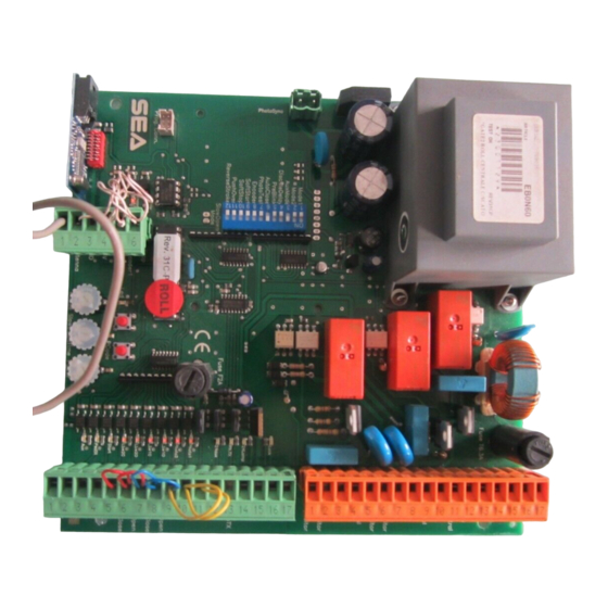
GATE 2 International registered trademark n. 2.777.971 PARTS SPECIFICATION LEDP LEDP GREEN ORANGE LED1 = Auxiliary input CN2 = 24V input / output connector (green) LED2 = Partial Start CN3 = Motors and Power supply connector (orange) LED3 = Start... -
Page 6: Connections
GATE 2 International registered trademark n. 2.777.971 CONNECTIONS (Green) 1 2 3 4 5 6 7 8 9 10 1112 13 14 15 16 17 ATTENTION NOTE: In the configuration of the swing gate double leaf the limit switches must not be bridged. -
Page 7: Slow-Down Mode, Dip Switches Logic Program
GATE 2 International registered trademark n. 2.777.971 SLOW-DOWN MODE, DIP SWITCHES, LOGIC PROGRAM Choose the slow down modality which can be more appropriate for the installation. Slow-down mode 1: Jumper unconnected (only DIP 10 ON) 2: Jumper connected 1 2 3 4 5 6 7 8 9... - Page 8 GATE 2 International registered trademark n. 2.777.971 DIP SWITCHES, LOGIC PROGRAM OPENED DIP 3 AND DIP 4 PROGRAMMING FOR AUXILIARY INPUT CONFIGURATION CLOSED SAFETY EDGE ( N.C. contact) When the Safety Edge Contact opens, the gate reverses direction and stops after about 1 second. A START command is required to restart movement TIMER (N.O.
-
Page 9: Operating Torque Adjustment
GATE 2 International registered trademark n. 2.777.971 TRIMMER REGULATION, LEDS OPERATING TORQUE ADJUSTMENT This trimmer is used to adjust the motor torque. This adjustment is essential for operators without mechanical or hydraulic anti-crush devices and must be carried out so that there is no risk of people or objects being crushed. -
Page 10: Radio Receiver, Start Button Connections
GATE 2 International registered trademark n. 2.777.971 RADIO RECEIVER, START BUTTON CONNECTIONS 1 2 3 4 5 6 7 8 9 10 11 12 13 14 15 16 17 Connection of a radio receiver This connection allows to command the total opening/closing of the automation. -
Page 11: Photocells, Buzzer Connections
GATE 2 International registered trademark n. 2.777.971 PHOTOCELLS, BUZZER, CONNECTIONS 1 2 3 4 5 6 7 8 9 10 11 12 13 14 15 16 17 Photocell self-testing Buzzer (24Vdc) Audible Alarm Use a buzzer 24V of 100 dB. The buzzer will be switched on after two consecutive activations of the anticrush sensor. -
Page 12: Electric Lock, Magnetic Lock Solenoid Lock Connections
GATE 2 International registered trademark n. 2.777.971 ELECTRIC LOCK, MAGNETIC LOCK SOLENOID LOCK CONNECTIONS 1 2 3 4 5 6 7 8 9 10 11 12 13 14 15 16 17 Electric lock exit An electric lock of 12V or of 24 Vdc 15W max can be connected .The electric lock... -
Page 13: Safety Edge, Flashing Lamp, Courtesy Light, Timer Connections
GATE 2 International registered trademark n. 2.777.971 SAFETY EDGE, FLASHING LAMP, COURTESY LIGHT, TIMER CONNECTIONS 1 2 3 4 5 6 7 8 9 10 11 12 13 14 15 16 17 Safety edge input Timer A further safety can be obtained making a connection with the safety edge mentioned on the side. -
Page 14: Power Supply, Motors, Capacitors Connections For Hydraulic Operators
GATE 2 International registered trademark n. 2.777.971 HYDRAULIC MOTORS, POWER SUPPLY, CAPACITORS CONNECTIONS 1 2 3 4 5 6 7 8 9 10 11 12 13 14 15 16 17 Capacitor 2 Capacitor 1 Motor 2 Output for Motor 2 connection... -
Page 15: Power Supply, Motors, Capacitors Connections For Alpha Operators
GATE 2 International registered trademark n. 2.777.971 MOTORS, CAPACITORS, POWER SUPPLY CONNECTIONS for ALPHA 1 2 3 4 5 6 7 8 9 10 11 12 13 14 15 16 17 Capacitor 1 Capacitor 2 Motor 2 Output for Motor 2 connection... -
Page 16: Antenna, Safety Gate, Stop Button Connections
GATE 2 International registered trademark n. 2.777.971 ANTENNA, SAFETY GATE, STOP BUTTON CONNECTIONS 1 2 3 4 5 6 LEDP Encoder adjustment procedure on board of the control unit 1. Keep pressed both Ptime and Pcode buttons for 3 seconds until ledP turns on.. -
Page 17: Self-Learning Of Operating Time For Swing Gates Operators
GATE 2 International registered trademark n. 2.777.971 SELF-LEARNING OF OPERATING TIMES FOR SWING GATES OPERATORS STEP 1 (Note: On swing gates with two leaves the limit switches have not to be bridged) Make all the electrical connections and jumpers on all the unused N.C. contacts (photocells, limit switches, etc). - Page 18 GATE 2 International registered trademark n. 2.777.971 SELF-LEARNING OF OPERATING TIMES FOR SWING GATES OPERATORS Press and Hold button P1 (LED P will come ON) until motor M2 will start to close the gate*. Release P1. LEDP If the motor start to open the gate, take OFF the power and reverse the motor phases.
- Page 19 FUNCTION OF THE CONTROL UNIT GATE 2 FOR ONLY ONE MOTOR The Gate 2 control unit can be used for the movement of one single leaf, when swing leaf it’s without limit switch. To prepare the control unit for the programming of this function it is sufficient to PUT A JUMPER between the limit switch contacts of the motor M1 (connected motor) and to exclude the leaf delay (Dip 4 ON).
-
Page 20: Programming A Transmitter On Start
GATE 2 International registered trademark n. 2.777.971 PROGRAMMING A TRANSMITTER WARNING: The default card will only accept ROLLING CODE radio transmitters (Ladbird Roll and and Smart Roll) associated with the RF ROLL (433 Mhz Code 23120470, 868 Mhz Code 23120480). To program “NOT ROLLING CODE”... -
Page 21: Loop Detector Wiring
GATE 2 International registered trademark n. 2.777.971 SAFETY LOOP CONNECTION DRAWING SHOWS HOW TO EVENTUALLY CONNECT THE MAGNETIC LOOP 1 2 3 4 5 6 7 8 9 10 11 12 13 14 15 16 17 C1 = CONTACT OPEN... - Page 22 GATE 2 International registered trademark n. 2.777.971 SAFETY LOOP CONNECTION CONNECTING SCHEME OF THREE READERS OF MAGNETIC LOOP DETECTORS: (TWO OF THEM USED AS SECURITY DEVICE AND ONE AS FREE EXIT) SAFETY LOOP SYSTEM EXIT LOOP SYSTEM REV 05 - 10/2010...
-
Page 23: Troubleshooting
GATE 2 International registered trademark n. 2.777.971 TROUBLESHOOTING Advises Make sure all Safety LED are turned ON All not-used N.C. contacts must have jumpers Problem Found Possibile Cause Solutions a) Check Connections or Jumpers on Contacts 9/11 - 10/11 on the Cn2... -
Page 24: Sales Conditions And Warranty
SEA. Recognized defects, whatever their nature, will not produce any responsibility and/or damage claims to SEA USA Inc and SEA s.r.l. Warranty shall not cover any required labor activities. Warranty will in no case be recognized if alterations and any other changes will be found on products. Warranty will not cover damages caused by carriers, expendable materials and faults due to improper use with the products specifications.
Need help?
Do you have a question about the GATE 2 and is the answer not in the manual?
Questions and answers