Table of Contents
Advertisement
EN
Please read this manual carefully to get the best performance from this unit.
Please keep this manual carefully.
Installation and operating instructions for the specialised installer
Valves, controls + systems
Istruzioni d'installazione e funziona-
IT
mento per l'installatore qualifi cato
Le istruzioni complete sono disponibili nel
seguente link: www.oventrop.com
http://www.oventrop.de/qr/138103081#IT
Instrucciones de instalación y opera-
ES
ción para el instalador especializado
El manual de instrucciones completo
se puede consultar en el siguiente link:
www.oventrop.com
http://www.oventrop.de/qr/138103081#ES
Инструкция по монтажу и эксплуа-
RU
тации для специалистов
Полное руководство по эксплуатации
можно найти по следующей ссылке:
www.oventrop.com
http://www.oventrop.de/qr/138103081#RU
Montážní a provozní návod pro od-
CS
borné pracovníky
Úplný návod k obsluze najdete na:
www.oventrop.com
http://www.oventrop.de/qr/138103081#CS
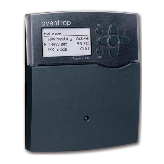
"Regtronic RQ"
Advertisement
Table of Contents

Related Manuals for oventrop Regtronic RQ

Summary of Contents for oventrop Regtronic RQ
- Page 1 Valves, controls + systems ”Regtronic RQ“ Installation and operating instructions for the specialised installer Istruzioni d’installazione e funziona- mento per l’installatore qualifi cato Le istruzioni complete sono disponibili nel seguente link: www.oventrop.com http://www.oventrop.de/qr/138103081#IT Instrucciones de instalación y opera- ción para el instalador especializado...
- Page 2 Safety advice Target group Disposal Please pay attention to the following safety advice These instructions are exclusively addressed to au- • Dispose of the packaging in an environmentally in order to avoid danger and damage to people and thorised skilled personnel. sound manner.
-
Page 3: Table Of Contents
Navigator Contents Installation ..........5 Installation page 5 Main functions ..........17 Mounting ............5 3.3.1 Hot water ........17 For mounting and connecting the controller, see Electrical connection........5 3.3.2 Circulation ........22 page 5. 3.3.3 Afterheating ........24 Commissioning .......... - Page 4 Overview Technical data Housing: plastic, PC-ABS and PMMA Inputs: 8 inputs for Pt1000 temperature sensors, input for Protection type: IP 20 / EN 60529 1 digital Grundfos Direct Sensor™ VFD 2 - 40 l Fast Protection class: I Outputs: 4 semiconductor relays, 1 PWM output Ambient temp.: 0 …...
-
Page 5: Installation
Installation 1.2 Electrical connection Mounting ATTENTION! ESD damage! The RQ DHW controller is already integrated in the Electrostatic discharge can lead to Regumaq DHW exchange module. If the controller is damage to electronic components! to be installed outside of the DHW exchange mod- Î... - Page 6 Vor Öffnen Gerät spannungslos schalten! Masse-Sammelklemme benutzen Isolate mains before removing cover! Use ground common terminal block 100 ... 240 V~ VN: 1.0 Masse-Sammelklemme benutzen Note: Mains and sensor cables are already connected to Note: 50-60 Hz Vor Öffnen Gerät spannungslos schalten! Use ground common terminal block 100 ...
-
Page 7: Commissioning
Commissioning c. Activating additional functions b. Activating the main functions When the hydraulic system is filled and ready for op- Only after the required main functions have been ac- eration, connect the controller to the mains. Adjustments for the main functions Circulation, tivated and adjusted, should the additional functions Afterheating and Disinfection can be made. -
Page 8: Operation And Function
Operation and function 2.2.2 Selecting menu points and adjusting 2.2.1 Buttons values The controller is operated via the 7 buttons next to During normal operation of the controller, the dis- play is in the main menu. If no button is pressed for a the display. - Page 9 Values and adjustments can be changed in different ways: adjusted value (not yet confi rmed) adjustment channel minimum maximum value value Some menu items are indicated with chackboxes. inactive area active area When an item has been selected, an x appears inside When two values are locked against each other, they the checkbox.
-
Page 10: Adjusting The Timer
2.2.3 Adjusting the timer Adding a time frame: When the Timer option is activated, a timer is in- dicated in which time frames for the function can be The time frames can be adjusted in steps of 15 min- adjusted. utes. - Page 11 Removing a time frame: In order to remove an active time frame, proceed as follows: Î Determine the point from which on the time frame is to be removed by pressing button ❸. Î Move the cursor to the desired ending point of the time frame by pressing buttons ❷...
-
Page 12: Menu Structure
2.2.4 Menu structure Main menu Status Status Hot water Hot water Meas. / Balance values Circulation Emergency operation Circulation Hot water T-HW set Afterheating Circ. mode Circulation Set min Disinfection Timer Afterheating Set max Additional functions Disinfection ∆Tmax Basic setting Function block 1 SD card HX start... -
Page 13: Commissioning Menu
Commissioning menu 1. Language: The commissioning menu consists of the channels Î Adjust the desired menu language. described here. They can be entered and adjusted line by line. 2. Daylight savings time adjustment: Î Activate or deactivate the automatical daylight savings time adjustment. - Page 14 5. Circulation: Î Activate the circulation and select the circula- tion mode. For detailed information see page 22. 8. Completing the commissioning menu: 6. Afterheating: If the security enquiry is confi rmed, the adjustments Î Activate the store afterheating. Adjust the after- are saved.
-
Page 15: Adjustments
Adjustments Status menu Main menu If, for example, Hot water is selected, a sub-menu In the Status menu of the controller, the status mes- with the sensors and relays allocated to the system sages for every menu area can be found. In this menu, the different menu areas can be se- will open. -
Page 16: Hot Water
3.2.2 Hot water 3.2.5 Disinfection 3.2.7 Messages In the Status / Hot water menu, the status of the In the Status / Messages menu, error and warning In the Status / Disinfection menu, the status and DHW heating is indicated. messages are indicated. -
Page 17: Main Functions
Main functions 3.3.1 Hot water • Emergency operation • Hot water set temperature • Minimum hot water set temperature • Maximum hot water set temperature • Maximum exceedance of the hot water set temperature • Heat exchanger mode start In this menu, all adjustments for the DHW heating •... - Page 18 Hot water set temperature (T -HW set) This parameter can be used for adjusting the T -HW set temperature which is to be reached at the HW fl ow sensor S2. The controller then determines the pump speed of the primary pump such that the tem- perature at the HW fl ow sensor on the secondary side continuously keeps the required set tempera- ture T-HW set.
- Page 19 Maximum limitation for exceedance of the hot water set temperature (T -HW set) This function can be used for preventing draw-off water temperatures that massively exceed the hot water set temperature ( scald protection). Note: The switch-on condition for the maximum limitation will only become valid if the hot water fl ow temperature is >= 60°C.
- Page 20 Heat exchanger mode The HX start sub-menu can be used to adjust all HX mode Cold values for the operation of the heat exchanger. The primary pump is only activated when there is a draw-off (cold start). At fi rst, the pump is run at the 3 heat exchanger modes are available.
- Page 21 Heat pump mode The HP mode can be used to force an afterheating, when a heat pump is used for the store afterheating. For that purpose, the store contents are mixed in or- der to decrease the store temperature, which leads to a heat pump demand.
-
Page 22: Circulation
3.3.2 Circulation Note: Note: The circulation function must be activated T -HW set is blocked against T -circ therm in order to use the thermal disinfection when the circulation mode Thermal is acti- function. vated. The set value can only be decreased down to a minimum limit which calculates as follows: T -circ therm + 2 K + ∆T circ... - Page 23 ∆T circ – circulation pipe temperature loss The ∆T circ adjustment value can be used to com- Î Read the correct value for ∆T circ from the ta- pensate the temperature loss in the circulation pipe. ble below. When the switching condition for a function is ful- During thermal disinfection,...
-
Page 24: Afterheating
3.3.3 Afterheating The Afterheating function can be used to reheat the upper store zone through a heat source, if necessary. It works independently from the hot water heating and can be activated by the user. When the function has been activated, the corre- sponding relay and the afterheating sensor have to be allocated. -
Page 25: Disinfection
3.3.4 Disinfection This function helps to prevent the spread of Legionella in DHW and circulation pipes on the secondary side of the heat exchanger. When the thermal disinfection function is active, the speed of the primary pump is controlled such that the adjustable temperature T -disinf set is reached. - Page 26 The thermal disinfection process When the preheating option is activated, the thermal The controller now aims to keep the required set 1. Store preheating disinfection will start automatically 30 minutes before temperature at the hot water flow sensor S2 and 2.
- Page 27 ∆T circ – circulation pipe time constant Time constant ∆t circ per 10 m copper pipe depending on the fl ow rate and for different pipe diameters The adjustment value ∆t circ determines the time a heat impulse needs to pass through the entire circulation pipe between the HW fl ow sensor and the circulation return sensor.
-
Page 28: Additional Functions
Additional functions Within a function block the functions are intercon- Timer nected (AND gate). This means that the conditions The relay allocated to the function block switches of all the activated functions have to be fulfi lled (e. g. on when the current operating time is within the ad- thermostat and timer) for switching the allocated re- justed time frame. - Page 29 As soon as at least one of the reference relays is ac- Note: tive, the switch-on condition for the reference relay If more than one function block has been function is considered unfulfilled. activated, relays of numerically higher func- tion blocks may not be used as reference In the AND mode, the switch-on condition for the relays.
- Page 30 Main menu / Additional functions / Function block Adjustment channel Description Adjustment range / selection Factory setting Function block 1 Activating the function block Yes, No Relay Relay system dependent system dependent Thermostat a Thermostat a Yes, No Th-a on Switch-on temperature Thermostat a -40 …...
- Page 31 Error relay The Error relay function can be used to operate a relay in the case of an error. Thus, e. g. a signalling device can be connected to signal errors. If the error relay function is activated, the allocated relay will switch on when an error occurs.
-
Page 32: Basic Settings
SD card Basic settings Reset By means of the reset function, all adjustments can be set back to their factory settings. All adjustments that have previously been made will be lost! For this reason, a security enquiry will appear after the reset function has been selected. Only confi rm the security enquiry if you are sure you want to set back all adjustment to the factory setting. - Page 33 Save adjustments. The content of the card will be deleted and the card named "OVENTROP / RQB" on the first While the adjustments are being stored, first Please will be formatted with the FAT file system.
-
Page 34: Manual Mode
Manual mode Note: When the operating mode for relay 4 is set to On, After service and maintenance work, the re- Emerg or Auto, the change only applies to the lay mode must be set back to Auto. Other- pump speed control signal sent to the primary pump wise normal operation will not be possible. -
Page 35: User Code
User code Inputs In the User code menu, a user code can be entered. In the Inputs menu, sensor offsets can be adjusted. Each number of the 4-digit code must be individually adjusted and confi rmed. After the last digit has been Inputs confi rmed, the menu automatically jumps to the su- perior menu level. -
Page 36: Data Communication
Data communication SD card slot Data communication / Bus The controller is equipped The controller is equipped with the S-Bus for data with an SD card slot. transfer with and energy supply to external modules. With an SD card, the following The connection is carried out at the two terminals functions can be carried out: marked “S-Bus”... -
Page 37: Troubleshooting
Troubleshooting If a malfunction occurs, a message will appear on the display of the controller. WARNING! Electric shock! Upon opening the housing, live parts are exposed! Î Always disconnect the controller from power sup- ply before opening the housing! The controller is protected by a fuse. The fuse holder (which also holds the spare fuse) becomes accessible when the cover is removed. -
Page 38: Overview Of Parameters
Overview of parameters Abbreviation Description ∆T absolute Afterheating temperature in the afterheating mode "Absolute" ∆T sliding Temperature difference for the sliding adaptation of the hot water set temperature ∆T relative Afterheating temperature in the afterheating mode "Relative" ∆T circ Temperature loss of the circulation pipe ∆t circ Time constant of the circulation pipe ∆Tmax... -
Page 39: Index
Index Mains connection ............6 Afterheating modes ............ 24 Manual mode ..............34 Meas. values ..............15 Balance values .............. 15 Boiler max..............24 Operating hours counter .......... 15 Operating mode, relays ..........34 Circulation ..............22 Commissioning menu ..........13 Preheating .............. - Page 40 OVENTROP GmbH & Co. KG Paul-Oventrop-Straße 1 D-59939 Olsberg Telephone +49 (0) 29 62 82-0 +49 (0) 29 62 82-400 E-mail mail@oventrop.de Internet www.oventrop.com Subject to technical modification without notice. For an overview of our global presence visit www.oventrop.com. 138103082...
Need help?
Do you have a question about the Regtronic RQ and is the answer not in the manual?
Questions and answers