Table of Contents
Advertisement
Quick Links
Advertisement
Table of Contents

Related Manuals for Pepperl+Fuchs PXV100AS-F200-SSI-V19


Summary of Contents for Pepperl+Fuchs PXV100AS-F200-SSI-V19
- Page 1 PXV100AS-F200-SSI-V19 DataMatrix Positioning System Manual...
- Page 2 Phone: +49 621 776 - 0 E-mail: info@de.pepperl-fuchs.com North American Headquarters Pepperl+Fuchs Inc. 1600 Enterprise Parkway Twinsburg, Ohio 44087 Phone: +1 330 425-3555 E-mail: sales@us.pepperl-fuchs.com Asia Headquarters Pepperl+Fuchs Pte. Ltd. P+F Building 18 Ayer Rajah Crescent Singapore 139942 Phone: +65 6779-9091 E-mail: sales@sg.pepperl-fuchs.com https://www.pepperl-fuchs.com...
-
Page 3: Table Of Contents
PXV100AS-F200-SSI-V19 Contents Introduction........................ 4 Content of this Document ................4 Target Group, Personnel ................4 Symbols Used ....................5 Product Description ....................6 Use and Application ..................6 USB Interface ....................7 SSI Interface ....................7 LED Indicators and Controls ................ 8 Accessories.................... -
Page 4: Introduction
PXV100AS-F200-SSI-V19 Introduction Introduction Content of this Document This document contains information required to use the product in the relevant phases of the product life cycle. This may include information on the following: • Product identification • Delivery, transport, and storage •... -
Page 5: Symbols Used
PXV100AS-F200-SSI-V19 Introduction Symbols Used This document contains symbols for the identification of warning messages and of informative messages. Warning Messages You will find warning messages, whenever dangers may arise from your actions. It is mandatory that you observe these warning messages for your personal safety and in order to avoid prop- erty damage. -
Page 6: Product Description
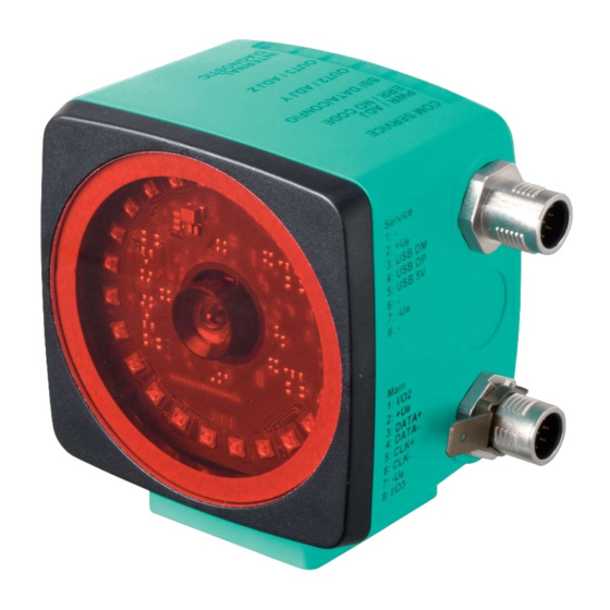
Product Description Use and Application The Data Matrix Positioning System is the positioning system in the Pepperl+Fuchs incident light process. The heart of the system is the reader, which has features including a camera module with an integrated illumination unit. This enables the reader to detect position markers printed onto a self-adhesive code tape in the form of 2-D Data Matrix codes. -
Page 7: Usb Interface
PXV100AS-F200-SSI-V19 Product Description USB Interface The Vision Configurator is a useful and easy-to-use piece of configuration software for con- figuring the reader. This configuration software is available as a free download from www.pep- perl-fuchs.com. Follow the instructions that appear on your screen during the installation. -
Page 8: Led Indicators And Controls
PXV100AS-F200-SSI-V19 Product Description LED Indicators and Controls The reader has seven indicator LEDs for carrying out visual function checks and rapid diagno- sis. Using the two control buttons on the rear of the device, you can activate the alignment aid and the parameterization mode. - Page 9 PXV100AS-F200-SSI-V19 Product Description Green/ Color Yellow yellow yellow yellow yellow yellow Description Status Off Flashes Alignment green Y > setpoint value = 2 Hz flash Flashes Alignment green Y < setpoint value = 2 Hz flash Flashes Flashes Off Alignment...
-
Page 10: Accessories
Accessories Compatible accessories offer you potential for cost savings when commissioning, replacing, and servicing our products. If products are used in harsh ambient conditions, appropriate Pepperl+Fuchs accessories can be used to extend the service life of these products. Model number... -
Page 11: Installation
PXV100AS-F200-SSI-V19 Installation Installation Affixing the Code Tape Dimensions of the Code Tape 000 000.0 m PXV-AA25 www.pepperl-fuchs.com The code tape is made of silicone-free polyester film. A position marker appears every 100 mm along the lower edge of the code tape (see "Code Tape Dimensions"). These position markers are used to affix the code tape in the correct position. - Page 12 PXV100AS-F200-SSI-V19 Installation Note Inclines and Declines If you affix the code tape on inclines or declines, cut the code tape several times at the transition point to the horizontal as shown. Figure 3.1 Schematic diagram: preparing Data Matrix code tape bends 1.
-
Page 13: Mounting The Reader
PXV100AS-F200-SSI-V19 Installation Mounting the Reader Mounting the Reader—The Process Make sure that you can mount the reader such that it has a stable position. Prior to mounting the reader, make sure that the guidance of the moving system component is such that the reader depth of focus range is not exited during operation. - Page 14 PXV100AS-F200-SSI-V19 Installation Reader Dimensions 38.5 14.5 Caution! When selecting the length of the mounting screws, ensure that the maximum insertion depth of the screws in the threaded inserts on the reader is 8 mm. Using longer screws can damage the reader.
-
Page 15: Electrical Connection
Connector Assignment Figure 3.5 Connector assignment Color Assignment Single-ended female cordsets by Pepperl+Fuchs are manufactured in accordance with EN60947-5-2. When using a type V19-... single-ended female cordset with an open cable end ( ), the following color assignment applies: Connection pin... - Page 16 PXV100AS-F200-SSI-V19 Installation Shielding Cables The shielding of connection lines is required to suppress electromagnetic interference. Estab- lishing a low resistance or low impedance connection with the protective conductor or equipo- tential bonding circuit is a particularly important factor in ensuring that these interference currents do not become a source of interference themselves.
-
Page 17: Commissioning
PXV100AS-F200-SSI-V19 Commissioning Commissioning Aligning the Read Head An integrated alignment aid is available to help you align the Y and Z coordinates of the read head easily and precisely with respect to the code reel. Note The activation of the alignment aid is possible only within 10 minutes of switching on the read head. - Page 18 PXV100AS-F200-SSI-V19 Commissioning Y coordinate: If the optical axis of the read head is too low relative to the middle of the code reel, the yellow LED4 lights up, . If the optical axis is too high, the yellow LED4 goes out. Within the target range, the yellow LED4 flashes at the same time as the green LED2.
-
Page 19: Parameterization
PXV100AS-F200-SSI-V19 Commissioning Parameterization The reader can be adapted to optimally meet specific requirements through parameterization. The reader can be parameterized via the service interface (internal parameterization) or via an optical parameterization code (external parameterization). 4.2.1 Internal Parameterization Using Parameterization Software Internal parameterization of the reader via the USB interface must be started within 10 minutes of the reader being switched on. -
Page 20: External Parameterization Using Code Cards
PXV100AS-F200-SSI-V19 Commissioning 4.2.2 External Parameterization Using Code Cards During external parameterization, the reader scans special code cards optically and configures the relevant parameters. Simply hold the corresponding code cards at the correct distance in front of the lens on the reader. The standard code cards are contained in the appendix. -
Page 21: The Code Cards "Cancel", "Use", And "Default
PXV100AS-F200-SSI-V19 Commissioning 4.2.2.1 The code cards "CANCEL", "USE", and "DEFAULT" Holding one of these cards in front of the reading head exits parameterization mode with the following consequences: • CANCEL: All parameter changes that are made but have not yet been saved are discarded. The reading head operates with the last valid parameters that were saved. -
Page 22: Operation And Communication
PXV100AS-F200-SSI-V19 Operation and communication Operation and communication Communication via the SSI Interface The reader has an SSI interface that enables it to read the current process data during opera- tion. This is an optically isolated RS422 interface. The controller sends a start sequence, and the reader responds synchronously with the 25 bit comprehensive data telegram. - Page 23 PXV100AS-F200-SSI-V19 Operation and communication You can define the structure and content of the response telegram using the configuration soft- ware Vision Configurator. This may include position data in an X- and Y-direction as well as speed and diagnostic data. Make sure that the required settings have been configured, trans- mitted to the reader, and stored there.
-
Page 24: Appendix
PXV100AS-F200-SSI-V19 Appendix Appendix Code Cards for External Parameterization Here, you can find the code cards that enable you to parameterize some basic read head func- tions step by step. For the exact external parameterization procedure . Note When performing external parameterization with code cards, we recommend copying and printing out the relevant pages in this manual and cutting out the code cards. - Page 25 PXV100AS-F200-SSI-V19 Appendix Store Store Figure 6.2 The "STORE" code card stores the modified parameterization in the nonvolatile memory of the read head and terminates external parameterization operating mode. Cancel Cancel Figure 6.3 The "CANCEL" code card discards the modified parameterization and terminates external parameterization operating mode.
- Page 26 PXV100AS-F200-SSI-V19 Appendix Default Default Figure 6.5 The "DEFAULT" code card restores the settings of the read head to default and terminates external parameterization operating mode.
-
Page 27: Code Cards For Adjusting The Resolution
PXV100AS-F200-SSI-V19 Appendix 6.1.2 Code Cards for Adjusting the Resolution Parameterization enables you to assign a position data resolution of 0.1 mm / 1 mm / 10 mm to the read head. Resolution: 0.1 mm Resolution 0.1 mm Figure 6.6 The code card assigns a position data resolution of 0.1 mm to the read head. - Page 28 PXV100AS-F200-SSI-V19 Appendix Maximum Length of the Code Tape Resolution of the read head [mm] Maximum length of the code tape [km]...
-
Page 29: Code Cards For Setting The Orientation
PXV100AS-F200-SSI-V19 Appendix 6.1.3 Code Cards for Setting the Orientation If the alignment of the read head to the code tape does not correspond to the default setting, the orientation must be adjusted. The orientation can be set at an angle of 0°, 180°, or 0°/180°. -
Page 30: Code Cards For Setting The Transfer Rate
PXV100AS-F200-SSI-V19 Appendix 6.1.4 Code cards for setting the transfer rate Parameterization allows you to assign various transfer rates to the reading head for communi- cation via the interface. The following transfer rates are available: • 38400 bit/s • 57600 bit/s •... - Page 31 PXV100AS-F200-SSI-V19 Appendix Transfer rate: 76800 bit/s 76800 Bit/s Figure 6.14 The transfer rate of the read head for communication via the interface is preset to 76800 bit/s. Transfer rate: 115200 bit/s 115200 Bit/s Figure 6.15 The transfer rate of the read head for communication via the interface is preset to 115200 bit/s.
-
Page 32: Code Cards For Adjusting Input/Output 3
PXV100AS-F200-SSI-V19 Appendix 6.1.5 Code Cards for Adjusting Input/Output 3 Parameterization enables you to assign various functions to input/output 3 on the read head. The following input/output functions are available: • Input: none • Output: Overspeed • Output: Warning • Output: Fault •... - Page 33 PXV100AS-F200-SSI-V19 Appendix Output 3: Warning Output 3 Warning Figure 6.19 Input/output 3 is defined as an output. This output carries the potential +U as long as a warning message is present in the read head. Output 3: Fault Output 3 Error Figure 6.20...
- Page 34 PXV100AS-F200-SSI-V19 Appendix Output 3: No position Output 3 No position Figure 6.22 Input/output 3 is defined as an output. This output carries the potential +U as long as the read head is not reading any position information.
- Page 35 Pepperl+Fuchs Quality Download our latest policy here: www.pepperl-fuchs.com/quality www.pepperl-fuchs.com © Pepperl+Fuchs · Subject to modifications Printed in Germany / DOCT-6766...
Need help?
Do you have a question about the PXV100AS-F200-SSI-V19 and is the answer not in the manual?
Questions and answers