Advertisement
Quick Links
Advertisement

Related Manuals for Pepperl+Fuchs PGV100-F200A-B25-V1D


Summary of Contents for Pepperl+Fuchs PGV100-F200A-B25-V1D
- Page 1 PGV100-F200A-B25-V1D Incident Light Positioning System Manual...
- Page 2 Phone: +49 621 776 - 0 E-mail: info@de.pepperl-fuchs.com North American Headquarters Pepperl+Fuchs Inc. 1600 Enterprise Parkway Twinsburg, Ohio 44087 Phone: +1 330 425-3555 E-mail: sales@us.pepperl-fuchs.com Asia Headquarters Pepperl+Fuchs Pte. Ltd. P+F Building 18 Ayer Rajah Crescent Singapore 139942 Phone: +65 6779-9091 E-mail: sales@sg.pepperl-fuchs.com https://www.pepperl-fuchs.com...
- Page 3 PGV100-F200A-B25-V1D Contents Introduction........................ 4 Content of this Document ................4 Target Group, Personnel ................4 Symbols Used ....................5 Product Description ....................6 Use and Application ..................6 LED Indicators and Operating Elements ............. 8 Accessories....................9 Installation........................ 10 Mounting the Read Head................10 Mounting the Colored Tape and Code Tape ..........
- Page 4 PGV100-F200A-B25-V1D Introduction Introduction Content of this Document This document contains information required to use the product in the relevant phases of the product life cycle. This may include information on the following: • Product identification • Delivery, transport, and storage •...
- Page 5 PGV100-F200A-B25-V1D Introduction Symbols Used This document contains symbols for the identification of warning messages and of informative messages. Warning Messages You will find warning messages, whenever dangers may arise from your actions. It is mandatory that you observe these warning messages for your personal safety and in order to avoid prop- erty damage.
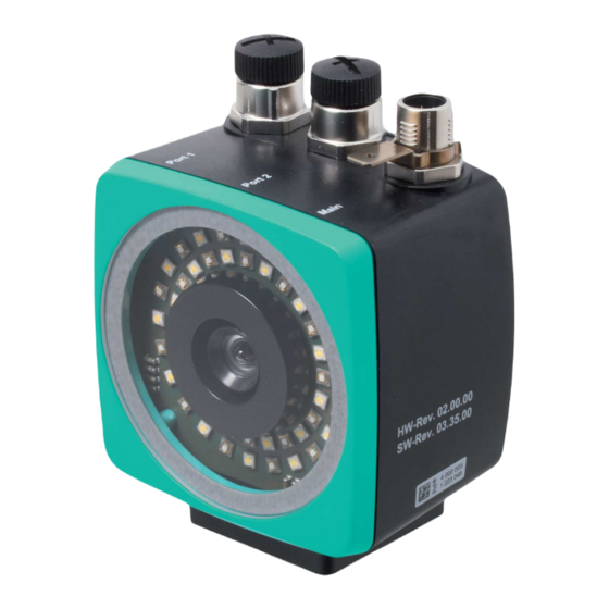
- Page 6 (AGV) are to be positioned pre- cisely at marked positions along a given lane. The read head forms part of the positioning system in the Pepperl+Fuchs incident light pro- cess. The read head's features include a camera module and an integrated illumination unit.
- Page 7 PGV100-F200A-B25-V1D Product Description Tag Mode In addition to the tracking, you can use the read head in tag mode. The read head detects Data Matrix tags, which are typically glued onto the floor in a grid. The individual Data Matrix tags are numbered consecutively and include position information.
- Page 8 PGV100-F200A-B25-V1D Product Description LED Indicators and Operating Elements The read head has six indicator LEDs for carrying out visual function checks and quick diagno- sis. Activate the alignment aid and parameterization mode using the two control buttons on the back of the device.
- Page 9 If products are used in harsh ambient conditions, appropriate Pepperl+Fuchs accessories can be used to extend the service life of these products.
- Page 10 PGV100-F200A-B25-V1D Installation Installation Mounting the Read Head Mount the PGV... read head on the automated guided vehicle using the four screws on the mounting adapter on the read head. Mount the read head in such a way that the lens with the ring light and camera module are directed toward the colored tape.
- Page 11 PGV100-F200A-B25-V1D Installation Read Head Dimensions 94.5 M6 x 9 (4x) Figure 3.1 Dimensions Caution! When selecting the length of the mounting screws, ensure that the maximum insertion depth of the screws in the threaded inserts on the read head is 8 mm.
- Page 12 Due to the integrated lighting of the read head, some floor colors appear to be different in the camera. If you have problems with the color selection of the colored tapes, please consult your contact at Pepperl+Fuchs. Mounting the Colored Tape Clean the surface of any greasy or oily deposits and dust.
- Page 13 PGV100-F200A-B25-V1D Installation Cleaning Colored Tape/Code Tape Significant contamination on the colored or code tapes can impair the detection by the read head. Clean the colored and code tapes with isopropanol if necessary. If the contamination is severe, you can use a non-corrosive plastic cleaner, e.g., Caramba®.
- Page 14 PGV100-F200A-B25-V1D Installation Angle Output Note Angles are specified as absolute values. The respective value is calculated from the resolution selected under "Angle Resolution". With a resolution of 0.1°, an angle of 60° is output as 60°/0.1° = 600. The read head detects a change of the angle of the colored tape and the Data Matrix code tape and outputs this value to the controller.
- Page 15 PGV100-F200A-B25-V1D Installation Data Matrix code tape The read head detects the absolute angle in relation to the tracked lane with a maximum reso- lution of 0.1°. The angle is specified absolutely relative to the tracked lane, since a Data Matrix code contains tape direction information.
- Page 16 PGV100-F200A-B25-V1D Installation Distance Output The read head detects the distance from the zero point in the Y direction of a colored tape or a Data Matrix code tape and outputs this value to the controller. The output value is different for colored tapes and Data Matrix code tapes due to the lack of an X position for colored tapes.
- Page 17 PGV100-F200A-B25-V1D Installation Data Matrix code tape The read head indicates the vertical distance of the zero point in relation to the Data Matrix code tape. Figure 3.7 Distance A for Data Matrix code tape...
- Page 18 PGV100-F200A-B25-V1D Installation Branches The read head detects one lane at the lower edge of the field of vision and two lanes at the upper edge of the field of vision; the read head indicates this as a branch. The read head detects two lanes at the lower edge of the field of vision and one lane at the upper edge of the field of vision;...
- Page 19 PGV100-F200A-B25-V1D Installation Code Tapes for Control and Positioning In addition to tracking the lane, the read head can also detect Data Matrix codes. This process involves evaluating both control and position information. Data Matrix control codes are used as event markers. Control codes provide information on branches. Data Matrix code tapes for positioning indicate the absolute position of the read head.
- Page 20 PGV100-F200A-B25-V1D Installation Branches or intersections with position information can be displayed as follows: Figure 3.9 Separate lane branches off/converges Figure 3.10 Same lane branches off/converges...
- Page 21 PGV100-F200A-B25-V1D Installation Note Direction Decision The direction decision at a branch of a Data Matrix code tape remains in effect until the read head has moved more than 50 cm from the branch. It is not possible to change the direction decision within a branch!
- Page 22 PGV100-F200A-B25-V1D Installation Behavior of the Read Head at Branches and Corners The read head behaves differently depending on the type of branch and the specified lane. The read head must know the upcoming direction decision. A second lane branches off to the left from the straight lane: The read head follows the straight lane if the direction decision "follow right-hand lane"...
- Page 23 PGV100-F200A-B25-V1D Installation Control codes can be mounted in the immediate vicinity of a branch with Data Matrix codes for positioning, but not near an intersection. The control code must be mounted directly next to the guiding lane. Figure 3.13 Branch with control code...
- Page 24 PGV100-F200A-B25-V1D Installation Distances To ensure that the read head can clearly detect and assign colored tapes and Data Matrix codes, minimum and maximum distances must be observed when creating the lanes. Offset V between position codes of a lane must not be greater than 5 mm.
- Page 25 PGV100-F200A-B25-V1D Installation The distance between the Data Matrix code tapes at a branch or intersection as a separate lane must be between 0 mm and 5 mm. Figure 3.16 Distance: 0 mm D 5 mm The distance between a colored tape and a Data Matrix control code must be between 0 mm and 5 mm.
- Page 26 PGV100-F200A-B25-V1D Installation The distance between a Data Matrix position code and a Data Matrix control code must be between 0 mm and 5 mm. 25 mm 25 mm 25 mm Figure 3.18 0 mm D 5 mm A lane can switch from a colored tape to a Data Matrix code tape and back again as often as required.
- Page 27 PGV100-F200A-B25-V1D Installation Caution! Alignment The Data Matrix code is not on the center line of the code tape. The code tape is made of silicone-free polyester film. A position marker appears every 100 mm along the lower edge of the code tape (see "Code Tape Dimensions"). This position marker is used for various functions, including precise positioning of the code tape during installation.
- Page 28 PGV100-F200A-B25-V1D Installation Data Matrix Code Tapes with a Starting Position of 0 m Order designation Description PGV10M-CA25-0 Code tape, length: 10 m PGV100M-CA25-0 Code tape, length: 100 m Table 3.3 See also data sheet PGV*-CA25-* at www.pepperl-fuchs.com Data Matrix control codes...
- Page 29 PGV100-F200A-B25-V1D Installation Data Matrix Tag A Data Matrix tag contains position information in addition to a specific number. A cross in the center of the Data Matrix tag marks the zero point. The X and the Y axes are marked starting from the zero point.
- Page 30 Plug assignment of the read head Color assignment Pepperl+Fuchs single-ended female cordsets are manufactured in accordance with EN60947- 5-2. When using a type V19-... single-ended female cordset with an open cable end (see chap- ter 2.3) on the Main connection, the following color assignment applies:...
- Page 31 PGV100-F200A-B25-V1D Installation Shielding Cables The shielding of connection lines is required to suppress electromagnetic interference. Estab- lishing a low resistance or low impedance connection with the protective conductor or equipo- tential bonding circuit is a particularly important factor in ensuring that these interference currents do not become a source of interference themselves.
- Page 32 PGV100-F200A-B25-V1D Installation EtherNet/IP Connection The read head is connected to EtherNet/IP via two 4-pin, D-coded connector sockets, M12 x 1, port 1 and port 2, on the side of the housing. TX + RX + TX - RX - Figure 3.24...
- Page 33 PGV100-F200A-B25-V1D Commissioning Commissioning Direction Decision The read head has several ways of following colored tapes and Data Matrix code tapes depending on the parameterization. Depending on the input signal, the read head follows the right-hand lane, the left-hand lane, or the better lane.
- Page 34 PGV100-F200A-B25-V1D Commissioning Following the Lane with Better Quality You can parameterize the read head so that it follows the color lane with better quality. Example Figure 4.2 1 - Better color lane 2 - Worse color lane...
- Page 35 PGV100-F200A-B25-V1D Commissioning Following the Lane with More Detailed Position Information You can parameterize the read head so that it follows the Data Matrix code tape that has more detailed current position information. Example Figure 4.3 1 - More detailed position information...
- Page 36 PGV100-F200A-B25-V1D Communication via EtherNet/IP Communication via EtherNet/IP General Information on Communication via EtherNet/IP The read head communicates with the controller (e.g., PLC) via EtherNet/IP. An object-oriented fieldbus system for exchanging data between nodes based on Ethernet technology. The management and development of the EtherNet/IP standards are subject to the Open Devi- ceNet Vendor Association (ODVA).
- Page 37 PGV100-F200A-B25-V1D Communication via EtherNet/IP Setting the IP Address The read head is delivered in DHCP mode and waits for an address assignment from the con- trol system. The following section describes the address assignment via the software BOOT/DHCP server from Rockwell Automation as an example.
- Page 38 PGV100-F200A-B25-V1D Communication via EtherNet/IP The read head cyclically carries out DHCP requests. This enters the MAC address of the read head in the Request History field to the list. Enter the desired IP address in the New Entry menu. - The software automatically adopts the MAC address of the read head.
- Page 39 PGV100-F200A-B25-V1D Communication via EtherNet/IP Press the Disable BOOTP/DHCP key in the Relation List field. In this way, the assigned IP address is saved permanently in the read head.
- Page 40 PGV100-F200A-B25-V1D Communication via EtherNet/IP EtherNet/IP Objects All the data and functions of the read head are defined via objects in accordance with the Eth- erNet/IP standards. The read head supports the following listed standard-specific classes. Standard Classes Class ID Class description...
- Page 41 PGV100-F200A-B25-V1D Communication via EtherNet/IP Cyclic Data Communication with Assembly Objects (Class Code 0x04) Assemblies are special CIP objects used for cyclic data communication (implicit messaging). Assemblies are composed of one or more attributes of various objects. These objects allow you to send or receive data from multiple objects via a connection.
- Page 42 PGV100-F200A-B25-V1D Communication via EtherNet/IP Instance Size Attribute Description [byte] Attribute Data type CCL status, CCL value CCL status USINT CCL value UINT Warning, error Warning UINT Error UINT Status, Y position, angle, X position, Z Status UINT distance, TAG number, CCL status,...
- Page 43 PGV100-F200A-B25-V1D Communication via EtherNet/IP EtherNet/IP Connections Configura- Output Input tion assem- Type Parameter assembly assembly Exclusive Status, Y position, angle owner Input only Status, Y position, angle Listen only Status, Y position, angle Exclusive Status, Y position, angle, warning, owner...
- Page 44 PGV100-F200A-B25-V1D Communication via EtherNet/IP Configura- Output Input tion assem- Type Parameter assembly assembly Listen only Status, Y position, angle, X posi- tion, Z value, tag value, CCL sta- tus, CCL value, warning, error Exclusive Status, Y position, angle, X posi-...
- Page 45 PGV100-F200A-B25-V1D Communication via EtherNet/IP Overview of the Attributes of EtherNet/IP Objects Read Head-Specific Attributes Data Size Type Attribute type [byte] Min. Max. Default Input Status word UINT Input Y position DINT Input Warning flags UINT Input Error flags UINT Input...
- Page 46 DataMatrix decoder switched off reserved reserved 1. If you have any questions, please contact Pepperl+Fuchs. Position/Lane You can use the following table to draw conclusions on the current section in the reading win- dow based on the feedback from the read head regarding Data Matrix tag TAG, No Lane NL, No X Position NP, absolute X position XP and the Y position and angle YPS/ANG.
- Page 47 PGV100-F200A-B25-V1D Communication via EtherNet/IP Number of Lanes LC (Lane Count) The lane count, LC, indicates the number of found fab or Data Matrix tracks in the reading win- dow. A variety of causes may be responsible if the lane count does not match the expected number of lanes: LC <...
- Page 48 PGV100-F200A-B25-V1D Communication via EtherNet/IP Warning: Warning Flags (ID 102) Size Type Content 2 byte consistent Input data Last warnings Last warning no. A set bit indicates that the corresponding warning is active. Warning Data Set Bit no. Content Description WRN01 A code with non-read head content was found.
- Page 49 PGV100-F200A-B25-V1D Communication via EtherNet/IP Angle data: Angle (ID 104) Size Type Content 2 byte consistent Input data 16 bit angle data LSB first LSB = least significant byte Resolution: 0.1°, 1° binary coded The following default settings apply: • The value is output in the set resolution of the device.
- Page 50 PGV100-F200A-B25-V1D Communication via EtherNet/IP ControlCode Status: CCL Status (ID 107) Size Type Content 1 byte Input data 8 bit status Bit 7 Bit 6 Bit 5 Bit 4 Bit 3 Bit 2 Bit 2 Bit 0 reserved reserved reserved Illumination control Orientation O The orientation O indicates the orientation of the control codes in the reading window.
- Page 51 PGV100-F200A-B25-V1D Communication via EtherNet/IP Side S Side S specifies the side of the Data Matrix lane on which the control codes are present. Meaning of Bits Meaning No control code is present or found Reserved Control code to the right of the Data Matrix lane...
- Page 52 PGV100-F200A-B25-V1D Communication via EtherNet/IP Direction Decision: Steering Information (ID 125) Bit 7 Bit 6 Bit 5 Bit 4 Bit 3 Bit 2 Bit 2 Bit 0 Reserved Reserved Reserved Lighting Reserved Reserved Select left Select control lane right lane Lighting control: •...
- Page 53 PGV100-F200A-B25-V1D Appendix Appendix ASCII table ASCII hex ASCII ASCII hex ASCII Space " & < >...
- Page 54 Pepperl+Fuchs Quality Download our latest policy here: www.pepperl-fuchs.com/quality www.pepperl-fuchs.com © Pepperl+Fuchs · Subject to modifications Printed in Germany / DOCT-6553...
Need help?
Do you have a question about the PGV100-F200A-B25-V1D and is the answer not in the manual?
Questions and answers