Table of Contents
Advertisement
Quick Links
Advertisement
Table of Contents

Subscribe to Our Youtube Channel
Related Manuals for Pepperl+Fuchs PXV F200-B25-V1D Series


Summary of Contents for Pepperl+Fuchs PXV F200-B25-V1D Series
- Page 1 FACTORY AUTOMATION MANUAL PXV...-F200-B25-V1D DataMatrix Positioning System...
- Page 2 PXV...-F200-B25-V1D With regard to the supply of products, the current issue of the following document is ap- plicable: The General Terms of Delivery for Products and Services of the Electrical Indus- try, published by the Central Association of the Electrical Industry (Zentralverband Elektrotechnik und Elektroindustrie (ZVEI) e.V.) in its most recent version as well as the supplementary clause: "Expanded reservation of proprietorship"...
-
Page 3: Table Of Contents
PXV...-F200-B25-V1D Introduction................. 4 Content of this Document ..............4 Target Group, Personnel..............4 Symbols Used ..................5 Product Description ..............6 Use and Application................6 USB Interface..................6 EtherNet/IP Interface Pin Assignment ..........7 LED Indicators and Controls............... 7 Accessories ..................9 Installation................. -
Page 4: Introduction
PXV...-F200-B25-V1D Introduction Introduction Content of this Document This document contains information required to use the product in the relevant phases of the product life cycle. This may include information on the following: Product identification Delivery, transport, and storage Mounting and installation ... -
Page 5: Symbols Used
PXV...-F200-B25-V1D Introduction Symbols Used This document contains symbols for the identification of warning messages and of informative messages. Warning Messages You will find warning messages, whenever dangers may arise from your actions. It is mandatory that you observe these warning messages for your personal safety and in order to avoid property damage. -
Page 6: Product Description
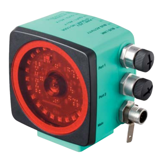
Product Description Use and Application The Data Matrix Positioning System is the positioning system in the Pepperl+Fuchs incident light process. The heart of the system is the reader, which has features including a camera module with an integrated illumination unit. This enables the reader to detect position markers printed onto a self-adhesive code tape in the form of 2-D Data Matrix codes. -
Page 7: Ethernet/Ip Interface Pin Assignment
PXV...-F200-B25-V1D Product Description 4. You can now connect the USB plug-in connector to your PC. EtherNet/IP Interface Pin Assignment The controller and read head communicate via the EtherNet/IP interface during operation. The interface is based on Ethernet technology and works according to the CIP protocol (Common Industrial Protocol). - Page 8 Lights up x EtherNet/IP- connection active Flashes EtherNet/IP TX/RX data transfer Flashes red Code not recognized = 2 Hz flash Lights up Lights up Internal error Return to Pepperl+Fuchs x = LED status has no meaning...
-
Page 9: Accessories
If products are used in harsh ambient conditions, appropriate Pepperl+Fuchs accessories can be used to extend the service life of these products. -
Page 10: Installation
PXV...-F200-B25-V1D Installation Installation Affixing the Code Tape The code tape is made of silicone-free polyester film. A position marker appears every 100 mm along the lower edge of the code tape (see "Code Tape Dimensions"). These position markers are used to affix the code tape in the correct position. The back of the code tape is covered with a modified acrylate-based adhesive designed for permanent adhesion. - Page 11 Installation Alignment of the Code Tape and Reader Position the code tape so that the PEPPERL+FUCHS logo and position markers are below the data matrix code. The position values then increase along the X direction. The diagram shows the orientation of a reader in the default setting of 0°. The reader can be configured in the interface for other installation situations.
-
Page 12: Mounting Of The Reader
PXV...-F200-B25-V1D Installation Hysteresis Y-Axis Figure 3.1 Zero line for code tapes If the reader leaves the zero line when traversing along the X-axis, the threshold may deviate. If the deviation exceeds the defined threshold, a warning code is issued. Y-Axis Deviation Thresholds Code Tape Threshold Number of Tracks... - Page 13 PXV...-F200-B25-V1D Installation 30° 30° Figure 3.3 Horizontal alignment tolerance Read Distance 4. Check that the distance between the reader and the code tape is equal to the read distance of the reader: Optimum Read Distance (Z-Axis) Order Designation Read Distance [mm] Depth of Focus [mm] PXV100* ±...
-
Page 14: Electrical Connection
Plug Assignment Main Color Assignment Pepperl+Fuchs single-ended female cordsets are manufactured in accordance with EN60947- 5-2. When using a type V19-... single-ended female cordset with an open cable end on the Main connection, the colors are assigned as follows: Connection Pin... -
Page 15: Ethernet/Ip Connection
PXV...-F200-B25-V1D Installation Shielding Cables The shielding of connection lines is required to suppress electromagnetic interference. Establishing a low resistance or low impedance connection with the conductor or equipotential bonding circuit is a particularly important factor in ensuring that these interference currents do not become a source of interference themselves. - Page 16 PXV...-F200-B25-V1D Installation Connector Assignment EtherNet/IP 1 & 2 Figure 3.5 Suitable Ethernet cables can be found in the Accessories section of the reader datasheet at www.pepperl-fuchs.com.
-
Page 17: Commissioning
PXV...-F200-B25-V1D Commissioning Commissioning Aligning the Reader The reader provides an integrated alignment aid to enable simple optimal alignment of the reader relative to the code tape in the Y-coordinate and the Z-coordinate. Note! The alignment aid may only be activated within 10 minutes of switching on the reader. You can also switch the reader from normal operation to parameterization mode, if necessary. -
Page 18: Operation And Communication
PXV...-F200-B25-V1D Operation and Communication Operation and Communication Communication via EtherNet/IP 5.1.1 General Information on Communication via EtherNet/IP The read head communicates with the controller (e.g., PLC) via EtherNet/IP. An object- oriented fieldbus system for exchanging data between nodes based on Ethernet technology. The management and development of the EtherNet/IP standards are subject to the Open DeviceNet Vendor Association (ODVA). - Page 19 PXV...-F200-B25-V1D Operation and Communication 1. Connect the read head with the DHCP server. 2. Start the BOOT/DHCP server software. 3. Enter the following data in the Network Settings menu: - Subnet Mask "255.255.255.0 " - Gateway "192.168.1.1" - the remaining fields are not filled in. 4.
- Page 20 PXV...-F200-B25-V1D Operation and Communication 6. Confirm the entries of the address data using OK. The IP address is assigned to the read head on the next DHCP request. The new address data will be displayed in the Relation List field. 7.
-
Page 21: Ethernet/Ip Objects
PXV...-F200-B25-V1D Operation and Communication 5.1.3 EtherNet/IP objects All the data and functions of the read head are defined via objects in accordance with the EtherNet/IP standards. The read head corresponds to the "Encoder Device Type 0x22" device profile. The read head supports the following listed standard and product-specific classes. Standard classes Class ID Class description... -
Page 22: Attributes Of The Reader's Ethernet/Ip Objects
PXV...-F200-B25-V1D Operation and Communication Cyclic data communication with assembly objects (Class Code 0x04) Assemblies are special CIP objects used for cyclic data communication (implicit messaging). These are composed of one or more attributes of various objects. These objects allow you to send or receive data from multiple objects by means of a connection. - Page 23 PXV...-F200-B25-V1D Operation and Communication Standard instance attributes for object 0x23 Attribute Access Data type Size [byte] Description Position Value DINT X position in two's Signed (X complement position) Velocity Value - DINT Velocity Reader-specific attributes Attribute Access Data type Size [byte] Description Status Word UINT...
- Page 24 PXV...-F200-B25-V1D Operation and Communication Position data Y: Y position (ID 101) Size Type Content 4 byte consistent Input data 32 bit Y data LSB first Resolution: 0.1 mm, 1 mm, 10 mm, binary coded in two's complement The following default settings apply: The Y position is output in the two's complement.
- Page 25 PXV...-F200-B25-V1D Operation and Communication Data for attribute 100 Content Byte 1, 2 Bit no. Status Function Error message (error code in XP00–XP15); remaining bits = 0, see Error Codes No position information/OUT (XP = 0, YP = 0, SP = 0) Warnings present, see Warning attribute Event, see Event attribute Posdetected...
- Page 26 PXV...-F200-B25-V1D Operation and Communication Warning: Warning Flags (ID 102) Size Type Content 2 byte consistent Input data Last warnings Last warning no. A set bit indicates that the corresponding warning is active. Data for attribute 102 Content Byte 1, 2 Bit no.
- Page 27 PXV...-F200-B25-V1D Operation and Communication Content Bit no. Byte 1, 2 Description WRN14 Reserved WRN15 Reserved WRN16 Reserved Note! If no warnings are present, all bits in the warning data set are set to 0.
-
Page 28: Appendix
PXV...-F200-B25-V1D Appendix Appendix ASCII Table ASCII ASCII ASCII hex ASCII Space " & < >... - Page 29 Twinsburg, Ohio 44087 · USA Tel. +1 330 4253555 E-mail: sales@us.pepperl-fuchs.com Asia Pacific Headquarters Pepperl+Fuchs Pte Ltd. Company Registration No. 199003130E Singapore 139942 Tel. +65 67799091 E-mail: sales@sg.pepperl-fuchs.com www.pepperl-fuchs.com Subject to modifications / DOCT-5912 Copyright PEPPERL+FUCHS • Printed in Germany 11/2017...
Need help?
Do you have a question about the PXV F200-B25-V1D Series and is the answer not in the manual?
Questions and answers