Table of Contents
Advertisement
Quick Links
Advertisement
Chapters
Table of Contents

Subscribe to Our Youtube Channel
Related Manuals for Pepperl+Fuchs PCV F200-B25-V1D Series


Summary of Contents for Pepperl+Fuchs PCV F200-B25-V1D Series
- Page 1 FACTORY AUTOMATION MANUAL PCV...-F200-B25-V1D Data Matrix Positioning System...
- Page 2 PCV...-F200-B25-V1D With regard to the supply of products, the current issue of the following document is ap- plicable: The General Terms of Delivery for Products and Services of the Electrical Indus- try, published by the Central Association of the Electrical Industry (Zentralverband Elektrotechnik und Elektroindustrie (ZVEI) e.V.) in its most recent version as well as the supplementary clause: "Expanded reservation of proprietorship"...
-
Page 3: Table Of Contents
PCV...-F200-B25-V1D Introduction................. 5 Declaration of conformity ............6 CE conformity..................6 Safety ................... 7 Symbols relevant to safety..............7 Intended use..................7 General safety instructions ..............7 Product Description ..............8 Use and Application................8 USB Interface..................8 EtherNet/IP Interface Pin Assignment ..........8 LED Indicators and Controls............... - Page 4 PCV...-F200-B25-V1D Operation and communication..........23 Communication via EtherNet/IP ............23 7.1.1 General Information on Communication via EtherNet/IP ....23 7.1.2 Setting the IP Address..............23 7.1.3 EtherNet/IP objects ................26 7.1.4 Attributes of the Ethernet/Read Head IP Objects......27 Operation with Repair Tape ...............33 Operating with event markers ............33 Appendix ...................
-
Page 5: Introduction
PCV...-F200-B25-V1D Introduction Introduction Congratulations You have chosen a device manufactured by Pepperl+Fuchs. Pepperl+Fuchs develops, produces and distributes electronic sensors and interface modules for the market of automation technology on a worldwide scale. Symbols used The following symbols are used in this manual: Note! This symbol draws your attention to important information. -
Page 6: Declaration Of Conformity
PCV...-F200-B25-V1D Declaration of conformity Declaration of conformity CE conformity This product was developed and manufactured under observance of the applicable European standards and guidelines. Note! A declaration of conformity can be requested from the manufacturer. -
Page 7: Safety
User modification and or repair are dangerous and will void the warranty and exclude the manufacturer from any liability. If serious faults occur, stop using the device. Secure the device against inadvertent operation. In the event of repairs, return the device to your local Pepperl+Fuchs representative or sales office. Note! Disposal Electronic waste is hazardous waste. -
Page 8: Product Description
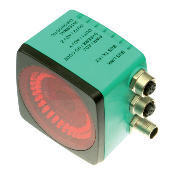
Use and Application The PCV read head is part of the positioning system in the Pepperl+Fuchs incident light process. Its features include a camera module and an integrated illumination unit, enabling it to detect position markers printed onto an adhesive code reel in the form of Data Matrix codes. - Page 9 PCV...-F200-B25-V1D Product Description ADJUST CONFIG Figure 4.1...
- Page 10 Lights up System error Lights up Normal operation, code tape detected green Lights EtherNet/IP-connection active Flashes EtherNet/IP TX/RX data transfer Code not recognized Flashes red = 2 Hz flash Internal error Return to Pepperl+Fuchs x = LED status has no meaning...
-
Page 11: Accessories
If products are used in harsh ambient conditions, appropriate Pepperl+Fuchs accessories can be used to extend the service life of these products. -
Page 12: Installation
PCV...-F200-B25-V1D Installation Installation Installing the Code Reel The code reel is made of silicone-free polyester film. A position marker appears every 100 mm along the lower edge of the code reel (see "Dimensions, Code Reel"). This position marker is used for various functions including precise positioning of the code reel during assembly. The reverse side of the code reel carries a permanent modified acrylate-based adhesive. - Page 13 PCV...-F200-B25-V1D Installation Orientation of the Code Reel and Read Head Figure 5.2 Position the code reel so that the www.pepperl-fuchs.com label and the position markings are below the data matrix code. The position values then increase along the X-direction. The diagram shows the orientation of a read head in the default position of 0°.
- Page 14 PCV...-F200-B25-V1D Installation Note! Inclines and Declines If you mount the code reel on inclines or declines, cut the code reel several times at the transition point to the horizontal as shown. 1. Incline 2. Decline Note! Code Reels with Different Row Numbers The PCV-CA20 code reel has two rows of code to compensate for slight deviations in the travel range in the Y-direction.
-
Page 15: Mounting The Read Head
PCV...-F200-B25-V1D Installation Hysteresis Y-Axis Figure 5.3 Zero line for code reels If the read head leaves the zero line when traveling the X-axis, different threshold values will result depending on the number of tracks. If the deviation exceeds this threshold, a warning code is issued. - Page 16 PCV...-F200-B25-V1D Installation 10° 10° Code reel Read distance Figure 5.4 Vertical alignment tolerance 10° 10° Figure 5.5 Horizontal alignment tolerance Optimum Read Distance (Z-Axis) Model Number Read Distance [mm] Depth of Focus [mm] PCV50* ± 25 PCV80* ± 15 PCV100* ±...
-
Page 17: Electrical Connection
PCV...-F200-B25-V1D Installation Read Head Dimensions 38.5 14.5 Figure 5.6 Caution! When selecting mounting screws, ensure that the maximum insertion depth of the screws in the threaded inserts on the read head is 8 mm. Using longer screws can damage the read head. Caution! The maximum torque of the mounting screws must not exceed 9 Nm. - Page 18 Connector Occupancy Main Figure 5.8 Color Assignment Pepperl+Fuchs cordsets (female) are manufactured in accordance with EN60947-5-2. When using a type V19-... () female cordset with an open cable end on the Main connection, the colors are assigned as follows: Connection pin...
-
Page 19: Ethernet/Ip Connection
PCV...-F200-B25-V1D Installation Caution! Damage to the device Connecting an alternating current or excessive supply voltage can damage the device or cause the device to malfunction. Electrical connections with reversed polarity can damage the device or cause the device to malfunction. Connect the device to direct current (DC). -
Page 20: Commissioning
PCV...-F200-B25-V1D Commissioning Commissioning Aligning the Read Head An integrated alignment aid is available to help you align the Y and Z coordinates of the read head easily and precisely with respect to the code reel. Note! The activation of the alignment aid is possible only within 10 minutes of switching on the read head. -
Page 21: External Parameterization Using Code Cards
PCV...-F200-B25-V1D Commissioning The Vision Configurator is a useful and easy-to-use piece of software for configuring the read head. This configuration software is available as a free download from www.pepperl- fuchs.com. Follow the instructions that appear on your screen during the installation. The PC connection required for programming and the read head power supply can be made using a special parameterization cable. - Page 22 PCV...-F200-B25-V1D Commissioning Programming mode activation Note! External parameterization of the read head using code cards must be started within 10 minutes of the read head switching on. A time lock disables the read head once this time has elapsed. The time lock remains inactive during the parameterization process. The time lock disables the read head only if no parameterization activities take place for more than 10 minutes.
-
Page 23: Operation And Communication
PCV...-F200-B25-V1D Operation and communication Operation and communication Communication via EtherNet/IP 7.1.1 General Information on Communication via EtherNet/IP The read head communicates with the controller (e.g., PLC) via EtherNet/IP. An object-oriented fieldbus system for exchanging data between nodes based on Ethernet technology. The management and development of the EtherNet/IP standards are subject to the Open DeviceNet Vendor Association (ODVA). - Page 24 PCV...-F200-B25-V1D Operation and communication 1. Connect the read head with the DHCP server. 2. Start the BOOT/DHCP server software. 3. Enter the following data in the Network Settings menu: - Subnet Mask "255.255.255.0 " - Gateway "192.168.1.1" - the remaining fields are not filled in. 4.
- Page 25 PCV...-F200-B25-V1D Operation and communication 6. Confirm the entries of the address data using OK. The IP address is assigned to the read head on the next DHCP request. The new address data will be displayed in the Relation List field. 7.
-
Page 26: Ethernet/Ip Objects
PCV...-F200-B25-V1D Operation and communication 7.1.3 EtherNet/IP objects All the data and functions of the read head are defined via objects in accordance with the EtherNet/IP standards. The read head corresponds to the "Encoder Device Type 0x22" device profile. The read head supports the following listed standard and product-specific classes. Standard classes Class ID Class description... -
Page 27: Attributes Of The Ethernet/Read Head Ip Objects
PCV...-F200-B25-V1D Operation and communication Cyclic data communication with assembly objects (Class Code 0x04) Assemblies are special CIP objects used for cyclic data communication (implicit messaging). These are composed of one or more attributes of various objects. These objects allow you to send or receive data from multiple objects by means of a connection. - Page 28 PCV...-F200-B25-V1D Operation and communication Standard instance attributes for object 0x23 Attribute Access Data type Size [byte] Description Position Value DINT X-Position in two's Signed (X- complement Position) Velocity Value - DINT Speed Specific read head attributes Attribute Access Data type Size [byte] Description Status Word...
- Page 29 PCV...-F200-B25-V1D Operation and communication Position data Y: Y position (ID 101) Size Type Content 4 byte consistent Input data 32-bit Y data LSB first Resolution: 0.1 mm, 1 mm, 10 mm, binary coded in two's complement The following default settings apply: The Y position is output in the two's complement.
- Page 30 PCV...-F200-B25-V1D Operation and communication Status: Status word (ID 100) Size Type Content 2 bytes Input data 16-bit status If the ERR bit is set, there is an error. The error number is transmitted to the "Value signed (ID 10)" attribute. Data of attribute 100 Content Byte 1, 2...
- Page 31 PCV...-F200-B25-V1D Operation and communication Event: Event marker no. (ID 103) Size Type Content 2 byte consistent Input data Last event marker Last event no. The event marker no. is binary coded and unsigned. Data of attribute 103 Content Byte 1, 2 Bit no.
- Page 32 PCV...-F200-B25-V1D Operation and communication Warning: warning flags (ID 102) Size Type Content 2 byte consistent Input data Last warnings Last warning no. A set bit indicates that the corresponding warning is active. Data of attribute 102 Content Byte 1, 2 Bit no.
-
Page 33: Operation With Repair Tape
PCV...-F200-B25-V1D Operation and communication Note! If no warnings are present, all bits in the warning data set are set to 0. Operation with Repair Tape The repair tape is a short code reel with a length of one meter. The repair tape is used to bridge defective or damaged areas of an existing code reel. - Page 34 PCV...-F200-B25-V1D Operation and communication When the reading head enters the range of an event marker, it sets an event flag in the output data. You also have the option of triggering a defined action when an event occurs by parameterizing one of the outputs accordingly (). Actions of this type can be initiated when a certain event, all events or events from an event list occur.
-
Page 35: Appendix
PCV...-F200-B25-V1D Appendix Appendix Code Cards for External Parameterization Here, you can find the code cards that enable you to parameterize some basic read head functions step by step. For the exact external parameterization procedure . Note! When performing external parameterization with code cards, we recommend copying and printing out the relevant pages in this manual and cutting out the code cards. - Page 36 PCV...-F200-B25-V1D Appendix The code card "CANCEL" Figure 8.3 The code card "CANCEL" discards the modified parameterization and terminates external parameterization operating mode. The reading head switches to normal mode and adopts the last valid configuration that was saved. The "USE" code card The "USE"...
-
Page 37: Code Cards For Adjusting The Resolution
PCV...-F200-B25-V1D Appendix 8.1.2 Code Cards for Adjusting the Resolution Parameterization enables you to assign a position data resolution of 0.1 mm / 1 mm / 10 mm to the read head. Resolution: 0.1 mm Figure 8.6 The code card assigns a position data resolution of 0.1 mm / 1 mm / 10 mm to the reading head. -
Page 38: Code Cards For Setting The Orientation
PCV...-F200-B25-V1D Appendix 8.1.3 Code Cards for Setting the Orientation If the alignment of the read head to the code tape does not correspond to the default setting, the orientation must be adjusted. The orientation can be set at an angle of 0°, 180°, or automatic detection in 90°... -
Page 39: Code Cards For Adjusting Output 1
PCV...-F200-B25-V1D Appendix 8.1.4 Code Cards for Adjusting Output 1 Parameterization enables you to assign various functions to output 1 on the read head. The following functions are available: None Speed exceeded Warning Fault Contamination Event No position Output 1: no function Figure 8.13 Output 1 has no function. - Page 40 PCV...-F200-B25-V1D Appendix Output 1: Fault Figure 8.16 Output 1 carries the potential +U as long as an error message is present on the read head. Output 1: Pollution Figure 8.17 Output 1 carries the potential +U as long as a pollution message is present on the read head.
-
Page 41: Code Cards For Adjusting Output 2
PCV...-F200-B25-V1D Appendix 8.1.5 Code Cards for Adjusting Output 2 Parameterization enables you to assign various functions to output 2 on the read head. The following input / output functions are available: Output: none Output: Overspeed message Output: Warning Output: Fault Output: Pollution Output: Event Output: No position... - Page 42 PCV...-F200-B25-V1D Appendix Output 2: Fault Figure 8.23 Input/output 2 is defined as an output. This output carries the potential +U as long as an error message is present on the read head. Output 2: Pollution Figure 8.24 Input/output 2 is defined as an output. This output carries the potential +U as long as a pollution message is present in the read head.
-
Page 43: Code Cards For Adjusting Output 3
PCV...-F200-B25-V1D Appendix 8.1.6 Code Cards for Adjusting Output 3 Parameterization enables you to assign various functions to output 3 on the read head. The following input / output functions are available: Output: None Output: Overspeed message Output: Warning Output: Fault Output: Pollution Output: Event Output: No position... - Page 44 PCV...-F200-B25-V1D Appendix Output 3: Fault Figure 8.30 Input/output 3 is defined as an output. This output carries the potential +U as long as an error message is present on the read head. Output 3: Pollution Figure 8.31 Input/output 3 is defined as an output. This output carries the potential +U as long as a pollution message is present in the read head.
-
Page 45: Ascii Table
PCV...-F200-B25-V1D Appendix ASCII table ASCII ASCII ASCII hex ASCII Space " & < >... - Page 46 Twinsburg, Ohio 44087 · USA Tel. +1 330 4253555 E-mail: sales@us.pepperl-fuchs.com Asia Pacific Headquarters Pepperl+Fuchs Pte Ltd. Company Registration No. 199003130E Singapore 139942 Tel. +65 67799091 E-mail: sales@sg.pepperl-fuchs.com www.pepperl-fuchs.com Subject to modifications / DOCT-4896A Copyright PEPPERL+FUCHS • Printed in Germany 09/2015...
Need help?
Do you have a question about the PCV F200-B25-V1D Series and is the answer not in the manual?
Questions and answers