Table of Contents
Advertisement
Quick Links
Advertisement
Table of Contents

Subscribe to Our Youtube Channel
Related Manuals for Advantech B+B SMARTWORX IE-iMcV-T1-Mux/4 +Ethernet


Summary of Contents for Advantech B+B SMARTWORX IE-iMcV-T1-Mux/4 +Ethernet
- Page 1 IE-iMcV-T1-Mux/4 +Ethernet USER MANUAL...
- Page 2 IE-iMcV-T1-Mux/4+Ethernet Advantech B+B SmartWorx - Americas 707 Dayton Road Ottawa, IL 61350 USA Phone (815) 433-5100 (815) 433-5105 Advantech B+B SmartWorx - Europe Westlink Commercial Park Oranmore, Co. Galway, Ireland Phone +353 91-792444 Fax +353 91-792445 www.advantech-bb.com support@advantech-bb.com...
-
Page 3: Table Of Contents
IE-iMcV-T1-Mux/4+Ethernet CONTENTS About T h e IE-iMcV-T1-Mux/4+Ethernet ............ 5 FEATURES ........................6 Managed Modules ....................... 7 Configuration Control ................7 1+1 Protection on Fiber Interface Mode ..............8 Serial Port Connection ....................9 iView² Management Software ..................9 LED Operation ..................10 10/100BaseT Connector ..................... - Page 4 IE-iMcV-T1-Mux/4+Ethernet SFP Line Status Screen ....................21 Ethernet Port Configuration Screen ................21 Ethernet Port Status Screen ..................22 T1 Port Configuration Screen ..................22 Host T1 Port Setup Screen ..................23 T1 Port Status Screen ....................23 Fiber Optic Port Verification ..................24 T1 Port Verification ....................
-
Page 5: About T H E Ie-Imcv-T1-Mux/4+Ethernet
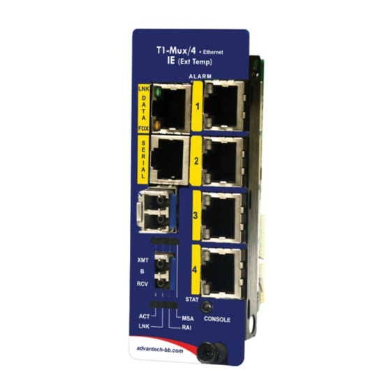
IE-iMcV-T1-Mux/4+Ethernet ABOUT T H E IE-IMCV-T1-MUX/4+ETHERNET The IE-iMcV-T1-Mux/4 + Ethernet is a media converter that transports four independent T1 lines over an existing single (or dual, “1+1”) standard fiber optic line operating at an effective rate of 155Mbps. One serial link (RS-232) and one Ethernet (10/100BaseT) connection are multiplexed onto the fiber link(s). -
Page 6: Features
IE-iMcV-T1-Mux/4+Ethernet FEATURES IE-iMcV-T1-Mux/4 + Ethernet offers the following features: • Four T1 ports with RJ-48 connectors • One full bandwidth Ethernet 10/100BaseT port • 1+1 protection switching via two SFP-based optical ports • DDMI supported on SFP ports • One end-to-end serial RS-232 port on RJ-45 connector; supports up to 120K baud rate •... -
Page 7: Managed Modules
IE-iMcV-T1-Mux/4+Ethernet MANAGED MODULES The IE-iMcV-T1-Mux/4 + Ethernet modules are installed as a Host/Remote pair; the fiber connection is B+B proprietary. Host or Remote configuration is selected by an onboard DIP Switch setting. The Host/Remote pair can be remotely managed when the HOST is installed in an iMediaChassis with an SNMP Management Module. -
Page 8: 1+1 Protection On Fiber Interface Mode
IE-iMcV-T1-Mux/4+Ethernet there is a mixture of iMcV modules, with and without Configuration Control, the Write Lock Switch and a new SNMP Management Module must be taken into consideration. If the command cleandb is applied to an SNMP Management Module, all the settings for the modules will be removed;... -
Page 9: Serial Port Connection
IE-iMcV-T1-Mux/4+Ethernet SERIAL PORT CONNECTION The IE-iMcV-T1-Mux/4 + Ethernet includes a console serial port. To establish a link between a module's console port and a local PC, connect the Mini Jack to DB9 adapter (optional accessory available through B+B SmartWorx, part number 825-39950). This RS-232 serial connection provides access to the IE-iMcV-T1-Mux/4 + Ethernet module CLI configuration screens. -
Page 10: Led Operation
IE-iMcV-T1-Mux/4+Ethernet LED OPERATION The IE-iMcV-T1-Mux/4 + Ethernet features diagnostic LEDs as explained below. 10/100BASET CONNECTOR LNK: • OFF when port is not linked/connected. • Glows green when link is established. • Blinks green during data activity. FDX: • OFF when port is not connected or when running at half-duplex. -
Page 11: Sfp Ports
IE-iMcV-T1-Mux/4+Ethernet SFP PORTS One model offers two SFP (A and B) ports for 1+1 protection; a second model offers one SFP without protection. ACT: • Glows green when the SFP port is the active receive line. • OFF when the SFP is not the receive line. •... -
Page 12: Dip Switch Assignments
IE-iMcV-T1-Mux/4+Ethernet DIP SWITCH ASSIGNMENTS A single 10-position DIP Switch is located on the unit to set configuration. The switch positions are as follows: Switch # Function Settings Factory Default Host/Remote OFF = Host, ON = Remote Reserved Reserved Reserved Reserved Reserved Reserved Reserved... -
Page 13: Installation Instructions
IE-iMcV-T1-Mux/4+Ethernet INSTALLATION INSTRUCTIONS Each IE-iMcV-T1-Mux/4 + Ethernet module requires two slots in an iMedia Chassis series, MediaChassis/2 series, or IE-MediaChassis/2 series. To install the module in a chassis: Remove the blank faceplates covering the slots where the module is to be installed. Then slide the module into the chassis card guides until the module is seated securely in the slots. -
Page 14: Configuration Options
IE-iMcV-T1-Mux/4+Ethernet CONFIGURATION OPTIONS The following sections describe the configurable features. From the CLI "Unit Configuration," use the "Factory Default" command to restore the unit's default settings in the CLI, under Unit Configuration. This restores the card's default configuration and resets the default username and password. -
Page 15: Fx Linkloss (Fxll)
IE-iMcV-T1-Mux/4+Ethernet that the cable coming from that device is intact. The appropriate “LNK” (link) LED is lit to indicate this. However, these signals are not normally transmitted across a normal store-and-forward Ethernet bridge function. A failed Ethernet line on one end of the fiber link is not forwarded to the Ethernet port at the other end of the optical transport. -
Page 16: Alarm Conditions
IE-iMcV-T1-Mux/4+Ethernet ALARM CONDITIONS • Last gasp (remote lost power) • T1 Port Up • T1 Port LOS • Fiber port Up / LOS • SFP removed/installed • Service state change LOOPBACK Each T1 port can be tested in loopback mode by enabling either a Host loopback or Remote loopback test path. -
Page 17: Console Screens
IE-iMcV-T1-Mux/4+Ethernet CONSOLE SCREENS CONFIGURATION USING THE CONSOLE PORT The following section describes configuration using the console screens. The Remote module is only configured through the Host. LOGIN SCREEN After running through an initial self test, the log-in screen is displayed. (The diagnostic information displayed below is for illustration purposes only and may differ from the actual screen display.) The username is case sensitive with a maximum length of 16 characters. -
Page 18: Main Menu
IE-iMcV-T1-Mux/4+Ethernet MAIN MENU From the main menu, the end-user can view essential unit configuration data and a clock indicating when the displayed information was last refreshed. Menu Options 1 = Refer to the Unit Configuration Screen. 2 = Refer to the Port Alarm Status screen. 3 = Refer to the SFP Line Status screen;... -
Page 19: Unit Configuration Screen
IE-iMcV-T1-Mux/4+Ethernet UNIT CONFIGURATION SCREEN The unit configuration screen displays the names of the Host and Remote units as well as the service state, whether fiber protection is enabled and the SFP BER alarm level. In addition, the unit time can be set from this screen and the username and password can be set/reset. -
Page 20: Port Alarm Status Screen
IE-iMcV-T1-Mux/4+Ethernet PORT ALARM STATUS SCREEN The Port Alarm Status screen displays the status of the Host and Remote alarms on each of the unit's ports. This screen can be refreshed, as needed, to display current data. -
Page 21: Sfp Line Status Screen
IE-iMcV-T1-Mux/4+Ethernet SFP LINE STATUS SCREEN The SFP Line Status screen displays the status of the Host and Remote SFP links. Detailed SFP information may be viewed by entering "1" for SFP A,, or "2" for SFP B. Displayed data includes the manufacturer name, code, part number and revision number. -
Page 22: Ethernet Port Status Screen
IE-iMcV-T1-Mux/4+Ethernet ETHERNET PORT STATUS SCREEN This screen displays the current Ethernet port status for both the Host and Remote site. T1 PORT CONFIGURATION SCREEN Use this screen to access the loopback and name details for each of the four T1 ports. Enter the number of the menu item to edit, and enter the new value(s) when prompted. -
Page 23: Host T1 Port Setup Screen
IE-iMcV-T1-Mux/4+Ethernet HOST T1 PORT SETUP SCREEN Enter the number of the menu item to edit, and enter the new value(s) when prompted. T1 PORT STATUS SCREEN Use this screen to display the current status for each of the four T1 ports for the Host and Remote units. -
Page 24: Fiber Optic Port Verification
IE-iMcV-T1-Mux/4+Ethernet FIBER OPTIC PORT VERIFICATION As a troubleshooting aid, the fiber optic ports can be verified by placing a physical loopback optical line on the ports and verify LED behavior as shown: The ACT LED will arbitrarily be configured to either the A or B fiber line. The RAI LED is RED/GREEN indicating that there is something wrong at the far end of the fiber line (in this case, the remote unit is missing). -
Page 25: T1 Port Verification
IE-iMcV-T1-Mux/4+Ethernet T1 PORT VERIFICATION By placing a physical loopback connection on the T1 port, a valid signal can be detected by each individual T1 port to verify its operation. Without the fiber looped, the ALARM LED for looped T1 port will show RED/GREEN indicating there is a problem at the far end of the fiber transport (In this case the far end unit is missing) and the STAT LED is RED because the fiber is in LOS. -
Page 26: T1 Port Mating Connector Pinout
IE-iMcV-T1-Mux/4+Ethernet T1 PORT MATING CONNECTOR PINOUT The following table lists the pin configuration for the standard RJ-48 T1 port mating connectors. Signal Receive 1 (Tip in to unit) Receive 2 (Ring in to unit) None Transmit 1 (Tip from unit) Transmit 2 (Ring from unit) None None... -
Page 27: Rs-232 Serial Console Port
IE-iMcV-T1-Mux/4+Ethernet RS-232 SERIAL CONSOLE PORT The following table lists the pin configuration for the RS-232 3-pin Mini Jack mating connector for the console serial port. DB9-F Pin# Signal Name Direction Transmit Out of Unit Ring Receive In to Unit Sleeve Return Return Sleeve... -
Page 28: Troubleshooting
IE-iMcV-T1-Mux/4+Ethernet TROUBLESHOOTING • All IE-iMcV-T1-Mux/4 + Ethernet units are shipped configured as Host units via DIP Switch #1 = OFF. The Remote unit should be set to DIP Switch #1 = ON. Be sure to confirm that the iMcV-T1-Mux/4 card is set correctly when used. •... -
Page 29: Definition Of Terms/Acronyms
IE-iMcV-T1-Mux/4+Ethernet DEFINITION OF TERMS/ACRONYMS The following are terms and phrases used in this manual, or found in documents associated with this equipment. The term “1+1” refers to line protection where identical information is transmitted on two redundant lines. The Receiver chooses the “best”... - Page 30 IE-iMcV-T1-Mux/4+Ethernet Fiber Fault Loopback - when the fiber line fails, the Ethernet port that is being forwarded over the fiber line is forced out of LINK. Similar to the Fiber Alert function. Graphical User Interface - software that provides a visual interface to enable an end-user to manage and monitor network devices.
- Page 31 IE-iMcV-T1-Mux/4+Ethernet Point(s) Of Presence - the demarcation point where carrier owned equipment is located at the customer site. Remote Alarm Indication - status information received from the line indicating there is an alarm condition at the far end of the transport. Small Form-Factor Pluggable - an industry standard optical pluggable module.
-
Page 32: B+B Smartworx Technical Support
USA/Canada: 1 (800) 346-3119 (Ottawa IL / USA) Europe: +353 91 792444 (Ireland / Europe) Email: support@advantech-bb.com Web: www.advantech-bb.com STATEMENTS, GUIDELINES, PRECAUTIONS FCC RADIO FREQUENCY INTERFERENCE STATEMENT This equipment has been tested and found to comply with the limits for a Class A computing device, pursuant to Part 15 of the FCC Rules. -
Page 33: Fiber Optic Cleaning Guidelines
IE-iMcV-T1-Mux/4+Ethernet FIBER OPTIC CLEANING GUIDELINES Fiber Optic transmitters and receivers are extremely susceptible to contamination by particles of dirt or dust, which can obstruct the optic path and cause performance degradation. Good system performance requires clean optics and connector ferrules. Use fiber patch cords (or connectors, if you terminate your own fiber) only from a reputable supplier;... -
Page 34: Electrostatic Discharge Precautions
IE-iMcV-T1-Mux/4+Ethernet ELECTROSTATIC DISCHARGE PRECAUTIONS Electrostatic discharge (ESD) can cause damage to any product, add-in modules or standalone units, containing electronic components. Always observe the following precautions when installing or handling these kinds of products: Do not remove unit from its protective packaging until ready to install. Wear an ESD wrist grounding strap before handling any module or component. -
Page 35: Standards/Compliances
© 2018 B+B SmartWorx – powered by Advantech. All rights reserved. The information in this document is subject to change without notice. B+B SmartWorx assumes no responsibility for any errors that may appear in this document. IE-iMcV-T1- Mux4-Ethernet is a trademark of B+B SmartWorx.
Need help?
Do you have a question about the B+B SMARTWORX IE-iMcV-T1-Mux/4 +Ethernet and is the answer not in the manual?
Questions and answers