
Related Manuals for Casio DT-X400 Series


Summary of Contents for Casio DT-X400 Series
- Page 1 Rugged Smart Handheld Terminal DT-X400 Series User’s Guide Be sure to read “Safety Precautions” inside this guide before trying to use your Rugged Smart Handheld Terminal.
- Page 2 Trademarks and Licenses Bluetooth is a registered trademark owned by Bluetooth SIG, Inc. and licensed to CASIO COMPUTER CO., LTD. Google™, the Google logo, Android™ and the Android logo are trademarks or registered trademarks of Google LLC. SD, SDHC, microSD and microSDHC are trademarks of SD-3C LLC.
-
Page 3: Table Of Contents
Contents Important ....................... E-2 Warning Label ....................E-3 Safety Precautions ..................E-3 Regulatory Information ................E-8 Operating Precautions ................. E-9 About the Waterproofing/Dustproofing ............ E-11 Accessories and Options ................E-12 Part Names ....................E-13 Getting Ready to Use ................. E-15 Attaching the screen protect sheet ............ -
Page 4: Important
Important Information in this document is subject to change without advance notice. CASIO Computer Co., Ltd. makes no representations or warranties with respect to the contents or use of this manual and specifi cally disclaims any express or implied warranties of merchantability or fi... -
Page 5: Warning Label
Safety Precautions Congratulations upon your selection of this CASIO product. Be sure to read the following Safety Precautions before trying to use it for the fi rst time. Your neglect or avoidance of the warning and caution statements in the subsequent pages causes the danger of fi... - Page 6 • Should the terminal and/or its options including battery pack and battery become hot or start to emit smoke or a strange odor, immediately turn off the power and contact your dealer or distributor whom you purchased the product from, or an authorized CASIO PA repair center. Foreign Objects •...
- Page 7 Warning LCD Screen • Never apply strong pressure to the screen or subject it to strong impact. Doing so can crack the LCD Screen. Prohibitions Should the LCD become cracked, never touch any of the liquid inside. • LCD liquid getting on the skin creates the risk of skin irritation. •...
- Page 8 • Do not use a battery that is severely swollen. Prohibitions • Replace only with the same type of battery pack recommended by CASIO. Dispose of used battery packs according to the local regulation. • Keep the battery pack out of the reach of small children.
- Page 9 Power Supply / AC Adapter Warning • Do not use the terminal at a voltage other than the specifi ed voltage. Also, do not connect the terminal to a multi-plug power strip. • Never modify, sharply bend, twist, or pull on the power cord. Prohibitions •...
-
Page 10: Regulatory Information
Backup of All Important Data Caution • Note that CASIO Computer Co., Ltd. shall not be held liable to you or any third party for any damages or loss caused by deletion or corruption of data due to use of the terminal, malfunction or repair of the terminal or its peripherals, or due to the batteries going dead. -
Page 11: Operating Precautions
Operating Precautions Your terminal and its options are precision. Improper operation or rough handling can cause problems with data storage and other problems. Note and observe the following precautions to ensure proper operation. • Do not continue using the battery once it is exhausted. Doing so could result in data loss or corruption. - Page 12 — If the battery pack is repeatedly charged, the life span becomes short. To avoid the repetition of charging the battery pack, be sure that the remaining capacity is low before you start charging. — Be sure to charge the battery pack in recommended temperature range. The temperature range is dependant on device you use to charge including battery chargers and tablets.
-
Page 13: About The Waterproofing/Dustproofing
The DT-X400 Series models are waterproof and dustproof. Important! The water- and dust-proofi ng performance of this product is based on CASIO testing procedures. Note also that this performance applies to the product at the time of shipment (delivery to the customer) and is not guaranteed inclusive of the environment in which the product is used. -
Page 14: Accessories And Options
Accessories and Options Rugged Smart Accessories Handheld Terminal Make sure all items listed below are included before using the DT-X400 Series terminal for the first time. • Hand Strap • Stylus (with retaining cord to prevent stylus loss) • Anti-slip Hook •... -
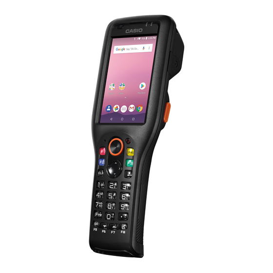
Page 15: Part Names
Part Names Smart Handheld Terminal (DT-X400) <Top> <Left> <Front> <Right> <Back> (With the battery pack cover fitted) 1 2 3 24 2526 <Bottom> <Back> (With the battery pack cover removed) The illustration shows DT-X400-WC21. E-13... - Page 16 Speaker Outputs alarm tones and other sounds. Charging Status LED Show charging status Notifi cation LED Show notifi cations Illuminance/ Measure brightness and proximity of object Proximity Sensor The screen displays texts, operations, indicators and so forth. In Screen (Touch Panel) addition, operations can be performed and data can be input on the screen using stylus.
-
Page 17: Getting Ready To Use
30 Battery Cover Lock Switch Open battery cover by sliding 31 Battery Cover Cover battery pack Strap Holes Used to attach the strap, hand belt hook and anti-slip hook. (Hand Belt Mount) Used for USB communication or to supply power to the terminal Power Supply/ and to charge the battery pack via either Cradle or Cradle-type Data Communication Terminal... -
Page 18: Attaching The Screen Protect Sheet
Attaching the screen protect sheet 1. Wipe off any dirt from the screen. 2. The screen protect sheet consists of three layers as shown in the fi gure. Screen protect sheet Release film Release film 3. Hold tape , remove the release fi lm ( ), and attach the screen protect sheet ( ) to the terminal. -
Page 19: Installing And Replacing The Battery Pack
Installing and Replacing the Battery Pack Your terminal uses two types of battery: a battery pack and a memory backup battery. The battery pack is used to power normal operations and to store data, while the memory backup battery provides the power required to maintain memory contents when the battery pack power is unable to supply power for some reason. - Page 20 Installation 1. Turn the terminal over, turn the left and right battery pack cover lock switches to the “FREE” position ( ) and remove the battery pack cover ( 2. Install the battery pack in the direction indicated by the arrow. 3.
- Page 21 Replacement 1. Turn the screen on. 2. Hold down the Power key until the Power menu is displayed. 3. Tap “Hot swap” as shown in the fi gure. 4. Tap “OK” as shown in the fi gure and the terminal will switch to the Hot Swap mode.
-
Page 22: Charging The Battery Pack
Charging the Battery Pack You can charge the battery pack while it is installed in the DT-X400 using the optional USB cradle, Ethernet cradle or multiple battery charger. Check charging status LED to confi rm DT-X400 charging status. You can also use the USB cradle, Ethernet cradle or dual battery charger to charge the battery pack. USB Cradle, Ethernet Cradle AC Adapter AD-S50400A... - Page 23 Multiple Battery Charger AD-S12500A • You can connect up to three Multiple Battery Chargers. Dual Battery Charger AD-S12500A • You can connect up to three Dual Battery Chargers. Charging status LED display for the four-bay battery charger Red: Charging Green: Charging complete Red/green alternate fl...
-
Page 24: Attaching The Stylus Strap
Attaching the Stylus Strap Use the procedure below to attach the stylus strap. Attaching the Hand Belt How to attach the Hand Belt 1. First check that the hand belt hook is oriented so that the projections are facing towards you, as shown in the illustration. -
Page 25: Attaching The Anti-Slip Hook
Removing the Hand Belt 1. Press on the projecting part of the terminal and disengage the metal hand belt fi tting, as shown in the illustration. 2. Peel apart the hook and loop fastener and pull the hand belt back through the hand belt hook. 3. -
Page 26: Calibrating Touch Panel Alignment
Calibrating Touch Panel Alignment Whenever the response of the touch panel is poor, or operation being executed does not match with the location you are tapping on the touch panel, please recalibrate the alignment of the touch panel using the following method. •... -
Page 27: Using The Laser Scanner (Dt-X400-10
Using the Laser Scanner (DT-X400-10) 1. After turning on the power, position the barcode reader close to a bar code and then press the trigger key. 2. The laser emits light and scans the bar code. If scanning is completed normally, Notifi cation LED displays a green light. - Page 28 Bar Code Scanning Position Position the laser scanner close to the bar code when scanning small bar codes. Position the laser scanner at a distance from the bar code so that the bars enter the light when scanning large bar codes. Margin Margin Good...
-
Page 29: Adjusting The Laser Light Emission Width
Adjusting the Laser Light Emission Width The emission width of the laser light emitted by the terminal can be adjusted. Adjust the emission width when it is improper. Before adjusting the laser, print out a copy of the emission width adjustment barcode on page E-28 enlarged to A4 size. -
Page 30: Using The Imager (Dt-X400-20/C21/Wc21/C31/Wc31
3. Press the trigger key to emit laser light, and align the light with the barcode for adjusting emission width. • Align the laser light with the narrow bars on both sides. • The message appears as shown at right when adjustment is completed. -
Page 31: Using A Sim Card
Using a SIM Card DT-X400 supports nanoSIM cards. To use WAN functions, a SIM card must be installed. The SIM card slot is located in the battery pack compartment, so you must remove the battery pack before installing or removing a SIM card. Installation 1. - Page 32 Removal 1. Turn the terminal off (shutdown). 2. Remove the battery pack. (Steps 5 and 6 in the battery pack replacement procedure on page E-19) 3. Flip back the SIM card cover. 4. Pull the SIM card out of the card slot, as shown in the fi gure. 5.
- Page 33 Precautions for Use • When installing a SIM card, check the orientation of the card and ensure that you install it correctly. Using excessive force when installing or removing a SIM card could damage the card. • Touching the IC area when installing a SIM card could result in damage to the card due to soiling or an electrostatic charge.
-
Page 34: Using A Microsd Card
Using a microSD Card DT-X400 supports micro SD cards. The microSD card slot is located in the battery pack compartment, so you must remove the battery pack before installing or removing a microSD card. Installation 1. Turn the terminal off (shutdown). 2. -
Page 35: Handling The Nfc
Handling the NFC The NFC is a technology of contactless IC card for short range communication that enables writing data to card and reading data from the card by applying the card close to the NFC Reader. The integrated NFC can read a contactless IC card used typically for employment identifi... -
Page 36: Turning The Power On/Off And Sleep
Turning the Power On/Off and Sleep Turning the Power On 1. Hold down the Power key until the terminal vibrates. • The startup screen is displayed. Precautions for Use • Be sure to completely charge the battery pack before turning the power on for the fi... -
Page 37: Performing Communications
Performing Communications ® Bluetooth Communication ® Bluetooth interface can also be used to transfer data between two terminals. ® With Bluetooth the two terminals should be located within about fi ve meters from each other, as long as there is nothing blocking the path between them. Important! Observe the following precautions to help ensure that Bluetooth communication is successful. -
Page 38: Rebooting Or Resetting The Terminal
Rebooting or Resetting the Terminal If the terminal no longer operates normally due to a problem such as an operating error or severe impact, use the procedure below to attempt to restore normal operation. 1. Reboot 2. Forced Reboot 3. Reset Reboot 1. -
Page 39: Dt-X400 Specifications
DT-X400 Specifications WC21 Remark 10-CN 20-CN WC31 ARM Cortex-A7 Microprocessor 1.3GHz Quad Core Android 8.1 Memory RAM: 2GB FROM: 16GB Display (3.2 inches), 480 x 800-dot TFT Color LCD 1D Scanner 2D Scanner Scanner *1 (Laser) (Imager) Camera – 8M pixels Auto Focus Microphone Voice sound input Speaker... - Page 40 WC21 Remark 10-CN 20-CN WC31 Dust / IP67 level water-resistance External dimensions Approx. 46mm x 197mm x 32mm Weight Approx. 260g Vibrator notifi cation of scanner Sensors Proximity sensor / Light Ambient sensor / Acceleration sensor Maximum monthly rate : 2min10sec (Use main battery) Maximum monthly rate : 8min38sec (Use sub batery only) E-38...
- Page 41 Scanner Specifi cations Item Specifi cation 1D Scanner Laser emit Redirected downward at 25 degree (Laser) angle Wave Length 645nm ~ 664nm Optical Output < 1.6mW No. of 100±20 scan/sec scanning Resolution 0.127mm(minimum) or greater 0.45(minimum) or greater Readable 43 ~ 890mm distance Readable maximum 670mm (at 890mm depth)
- Page 42 Item Specifi cation UPC-A/UPC-E/EAN8 (JAN8)/EAN13 (JAN13)/Codabar (NW-7)/Code39/ Interleaved2of5 (ITF)/MSI/ISBT/Code93/Code128/GS1-128 (EAN128)/ Readable 1D GS1 DataBar Omnidirectional (RSS-14)/ symbologies GS1 DataBar Limited (RSS Limited)/ GS1 DataBar Expanded (RSS Expanded)/Code32/GS1 DataBar Truncated PDF417/Micro PDF/Composite/Codablock F/ Readable GS1 DataBar Stacked Omnidirectional (RSS-14 Stacked)/ Stacked 2D GS1 DataBar Expanded Stacked (RSS Expanted Stacked)/ symbologies GS1 DataBar Stacked (RSS-14 Stacked)/GS1 DataBar Truncated...
- Page 43 Wireless WAN Specifi cations Item Specifi cation Communication Audio, Data Packet Downlink: 150Mbps (maximum) Baud rate Uplink: 50Mbps (maximum) FDD 1 (1920-1980MHz/2110-2170MHz) FDD 3 (1710-1785MHz/1805-1880MHz) FDD 7 (2500-2570MHz/2620-2690MHz) FDD 8 (880-915MHz/925-960MHz) Frequency FDD 19 (830-845MHz/875-890MHz) range Band FDD 20 (832-862MHz/791-821MHz) FDD 26 (814-849MHz/859-894MHz) TDD 38 (2570-2620MHz/2570-2620MHz) TDD 41 (2496-2690MHz/2496-2690MHz)
- Page 44 NFC Spefi cications Item Specifi cation Remark ISO14443 Type A/B, FeliCa: It can change 0 mm (Contact) by the design Depth of Field of Card or ISO15693: 0 mm (Contact) ~ 50 mm (Maximum) According to JEITA G mode LCD backlight brightness minimum, WLAN ON (with stable RF connection), Buzzer minimum, Vibrator OFF, RF OFF (except for WLAN), Power saving setting after laser scanning (1sec) •...
-
Page 45: Installing And Removing The Ac Adapter For The Usb And Ethernet Cradles
Installing and Removing the AC Adapter for the USB and Ethernet Cradles The AC adapter for the USB and Ethernet cradles must be fi tted with a suitable power plug for the region where the terminal will be used. Installation 1. -
Page 46: Usb Cradle (Ha-S60Io
USB Cradle (HA-S60IO) The USB cradle can be used to connect the DT-X400 to devices such as a computer or USB device. It can also be used to supply power to the DT-X400 and to charge the battery pack. Part Names and Operation <Top>... - Page 47 4. Align the terminals on the bottom of the DT-X400 with the power supply terminals in the USB Cradle before inserting the DT-X400 ( Push the DT-X400 fully into the USB Cradle until the mount hooks in the cradle engage the mount holes in the DT-X400( To remove the DT-X400 from the USB Cradle, tilt the DT-X400 forward to disengage the mount...
-
Page 48: Ethernet Cradle (Ha-S62Io
Ethernet Cradle (HA-S62IO) The optional Ethernet Cradle (HA-S62IO) makes it possible to transmit fi le data between DT-X400 and a PC via a USB or LAN connection (download or upload). You can also use the Ethernet Cradle to charge the battery pack installed in DT-X400. Part Names and Operation <Top>... - Page 49 Installing and Connecting the Power Supply Use the optional AC adaptor(AD-S50400A) to supply power to the charger. Use the selector switch on the left side of the Ethernet Cradle to select the port to be used. Set the switch to the “LAN” position when using the LAN port on the cradle.
- Page 50 Precautions for Use • Even if the battery in the DT-X400 is already fully charged, charging will begin when you set the DT-X400 in the Ethernet cradle. It may take several minutes for the fully charged status to be indicated. •...
-
Page 51: Multiple Battery Charger (Ha-S36Dchg
Multiple Battery Charger (HA-S36DCHG) The optional Multiple Battery Charger (HA-S36DCHG) can concurrently charge two battery packs installed in the respective DT-X400s. Part Names and Operation <Side> <Top> <Bottom> E-49... - Page 52 Accessories Use these bundled items to join multiple chargers together. • Bottom bracket • Side bracket • Screws (for brackets) Two each for one bracket AC Adaptor Jack Connect the AC adaptor (sold separately) here. Power Switch Turns the power on and off . Multiple Battery Charger Use these connectors to connect Multiple Battery Chargers to each Connection Port...
- Page 53 Charging Battery Pack Use the optional AC adaptor(AD-S12500A) to supply power to the charger. AD-S12500A 1. Plug the connector from the AC adaptor into the AC adaptor jack on the charger with the engraved side of the connector facing upwards. Push the connector fi rmly into the jack until it clicks into place.
- Page 54 Connecting Multiple Battery Chargers You can connect up to three Multiple Battery Chargers. Doing so makes it possible to supply power to all the Multiple Battery Chargers using one dedicated AC adaptor. 1. As shown in the illustrations below, remove the connector covers of the Multiple Battery Chargers you want to connect to each other.
- Page 55 Precautions for Use • Each unit of the charger comes with one piece each of the side and bottom brackets. After you join two chargers together using these two brackets, one side bracket and one bottom bracket will be left over. Keep these as spare for use in future. •...
-
Page 56: Dual Battery Charger (Ha-S32Dchg
Dual Battery Charger (HA-S32DCHG) The optionally available Dual Battery Charger (HA-S32DCHG) can be used to simultaneously charge two battery packs. Part Names and Operation <Left> <Top> <Right> <Bottom> Accessories Use these bundled items to join multiple chargers together. • Bottom bracket •... - Page 57 Off : The battery pack is not installed. Red: Charging Green: Charging complete Red/green alternate fl ashing: Standby because the battery pack is faulty, Charging Status LED is installed incorrectly or is outside the charging temperature range (Charging begins when temperature returns to the charging temperature range) AC Adaptor Jack Connect the AC adaptor (sold separately) here.
- Page 58 Charging status LED display for the four-bay battery charger Off : The battery pack is not installed. Red: Charging Green: Charging complete Red/green alternate fl ashing: Standby because the battery pack is faulty, is installed incorrectly or is outside the charging temperature range (Charging begins when temperature returns to the charging temperature range) Connecting Multiple Dual Battery Chargers...
-
Page 59: Usb Type-C Cable (Ha-S81Usbc
Specifications 1. Charging specifi cations Charging method : Constant-voltage constant-current charging Charging time : Approx. 4 hours 2. AC adapter specifi cations Standard : AD-S12500A Input : 100-240V AC, 50/60 Hz, 1.5A Output : 12V DC, 5A 3. Operating environment Operating temperature : 0°C to 40°C Operating humidity : 20-90% RH (condensation-free) -
Page 60: Battery Pack (Ha-S20Bat
If the battery pack fails to hold its operating duration after it has been fully charged, replace it with a new one. The battery pack may reach the end of its service life. • When buying a battery pack, you should purchase a Casio genuine battery pack. Battery Pack Specifications Model:... - Page 61 CASIO COMPUTER CO., LTD. 6-2, Hon-machi 1-chome Shibuya-ku, Tokyo 151-8543, Japan PN430149-001 MO1812-A 2018 CASIO COMPUTER CO., LTD.
Need help?
Do you have a question about the DT-X400 Series and is the answer not in the manual?
Questions and answers