
Related Manuals for Casio DT-930M50E


Summary of Contents for Casio DT-930M50E
- Page 1 数据采集器免费服务热线:400-1166-021 Handheld Terminal Series User’s Guide Data Collection Terminal...
- Page 2 · Be sure to read "Safety Precautions" inside this guide before trying to use your Handheld Terminal. After reading this guide, keep it in a safe place for future reference. PN430041-001...
- Page 3 BLUETOOTH is a registered trademark owned by Bluetooth SIG. Inc. and licensed to CASIO COMPUTER CO., LTD.
- Page 4 Safety Precautions Congratulations upon your selection of this CASIO Product. Be sure to read the following Safety Precautions before trying to use it for the first time. Keep this manual in a handy place for future reference. Markings and Symbols possibility of personal injury and/or material damage or loss to you and others.
- Page 5 Danger! ■ Lithium-ion Battery Pack The Lithium-ion Battery Pack is available as an option. ● Never allow the battery pack to become wet. Water can create the danger of battery pack heat emission, explosion, and fire. ● Never use or leave the battery pack next to open flame, near a stove, or any other area exposed to high heat.
- Page 7 ● Should the unit become hot or start to emit smoke or a strange odor, immediately turn off the power and contact your original dealer or an authorized CASIO service provider. Continued use creates the danger of fire and electrical shock.
- Page 8 Warning! ■ Interference with the Operation of Other Equipment (Using Wireless Communication) ● Keep your Handheld Terminal at least 22 centimeters (8' 1/10") away from anyone wearing a pacemaker. Radio waves emitted by the Handheld Terminal can affect the operation of a pacemaker. ●...
- Page 10 Warning! ■ Handling the Coin Type Lithium Battery ● Do not recharge coin type lithium battery. Doing so may cause it to leak fluid, overheat, explode or burst into flames. ● Do not put the coin type lithium battery in open flame, or apply solder directly to the coin type lithium battery.
- Page 11 ● Should the power cord ever become severely damaged (to the point that wires are exposed or broken), contact your original dealer or CASIO service provider for repair or replacement. Use of a damaged electrical cord creates the danger of fire and electrical shock.
- Page 12 Caution! ■ LCD Screen ● Never apply strong pressure to the screen or subject it to strong impact. Doing so can crack the LCD panel glass and create the danger of personal injury. ● Should the LCD panel glass ever break, never touch the liquid inside. Doing so can cause skin irritation and inflammation.
- Page 13 Caution! ■ Handling Alkaline Batteries ● Store batteries someplace out of direct sunlight where the temperature and humidity are not high. Not doing so may cause the batteries to leak fluid, overheat or explode. Also, it may cause the life and performance of the batteries to decline.
- Page 14 E-10...
- Page 15 Make back-up copies of all important data Caution! ● Note that CASIO Computer Co., Ltd. shall not be liable to you or any third party for any damages or loss caused by deletion or corruption of data due to use of this, malfunction or repair of this unit or its peripherals, or due batteries going dead.
-
Page 16: Handling Precautions
Introduction Make sure you carefully read the following information to ensure that your Handheld Terminal is able to perform at the level for which it is designed. Handling Precautions · Do not throw or drop the Handheld Terminal or otherwise subject it to strong impact, which can damage the LCD screen, interrupt program execution, corrupt memory contents, or otherwise interfere with proper operation. - Page 17 E-12...
- Page 18 Product description/Intended use EU/EFTA member states intended for use Spain, Sweden, United Kingdom, Czech Republic, Hungary, Poland, Slovenia, Slovakia, Estonia, Latvia, Lithuania, Cyprus, Malta EFTA: Switzerland, Iceland, Lichtenstein, Norway Member states with restrictive use Manufacturer Brand Type are tested and found to conform with the essential requirements for protection of health and the safety of the user and any other persons and Electromagnetic Compatibility, as included in following standards: Standard...
- Page 19 E-13...
-
Page 20: Table Of Contents
· The contents of this manual are subject to change without notice. · The term “Handheld Terminal” as used in this User’s Guide refers to the CASIO DT-930 Handheld Terminal unless otherwise noted. · CASIO COMPUTER CO., LTD. assumes no responsibility for any loss or claims by third parties which may arise from the use of this manual. - Page 21 Functions ........E-27 Using Code Reader ....... E-28 Performing Code Read Operation ......E-28 Adjusting Laser Beam Width ......... E-30 Communications ..........E-32 Communication ............... E-32 Bluetooth ® Communication ..........E-33 Specifications ............. E-34 Lithium-Ion Battery Pack (DT-923LIB) .........
- Page 22 Using Basic Cradle ........E-42 General Guide ..............E-42 When You Are Using the Down-facing Reader Port Model .. E-44 Setting Basic Cradle ..........E-44 Serial Connection Multiple Basic Cradles ......E-46 Switch Settings ............. E-46 DT-960IOE Basic Cradle Specifications ......
- Page 23 Guide ..............E-59 When You Are Using the Down-facing Reader Port Model .. E-60 Setting Cradle-type Battery Charger ......E-60 Charging the Battery Pack (charging the lithium-ion battery pack separately) ..E-63 DT-969CHGE Cradle-type Battery Charger Specifications . E-65 Installing Cradles and Cradle-type Battery Charger ...
-
Page 24: Unpacking
Unpacking When unpacking the Handheld Terminal (either DT-930M50E or DT-930M51E), check carefully that all of the items shown below are included. If anything is missing or damaged, contact your original dealer or your nearest CASIO Service Provider. · Handheld Terminal... -
Page 25: Available Models
Available Models and Options Options Bridge Basic Cradle HA-E60IO DT-930 M50E DT-930 M51E E-17... - Page 26 AC Adaptor for Bridge Basic Cradle AC Adaptor for Basic Cradle AD-S15050AE DT-9020 ADP-GS DT-9020ADP-US AC adaptor for Satellite Cradle AC adaptor for Cradle-type Battery Charger AD-S42120AE DT-9020 ADP-GS DT-9020ADP-US RS-232Ccable DT-782RSC (Male) RS-232Ccable DT-783RSC (female) RS-232Ccable DT-787AX (female) RS-232Ccable DT-881RSC connection RS-232Ccable...
-
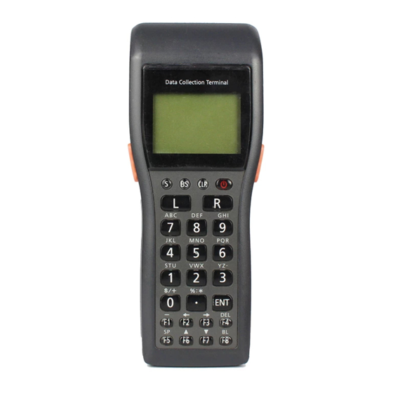
Page 27: General Guide
General Guide Left side read, red when the read is no good. other operations. located inside the hole. - Page 28 the buzzer holes and reducing output sound volume. Never insert any thin, pointed object into the buzzer holes. Doing so can cause malfunction. 10 Back-up battery compartment 11 Main battery compartment 12 Main battery compartment lock Locks the main battery compartment cover in place. Handheld Terminal power is automatically cut if the cover is removed.
-
Page 29: Power Supply
Power Supply The Handheld Terminal has both operating power supply provided by either two AA (LR6)-size alkaline batteries or lithium-ion battery pack, and memory backup power supply provided by lithium battery. In this manual, the words "main battery" refer to both alkaline batteries and the lithium-ion battery pack, unless otherwise noted. - Page 30 replace it with a new one. The battery pack may reach the end of its E-20...
-
Page 31: Loading And Removing The Aa (Lr6)-Size Alkaline Batteries
Loading and Removing the AA (LR6)-size alkaline batteries Important! their positive (+) and negative (–) ends are facing the correct directions. Loading the alkaline batteries lock to the FREE position and remove the cover. into the main battery compartment, making sure that they face the directions shown in the figure. - Page 32 Remove the alkaline batteries following the loading procedure in reverse. Be sure to turn the Handheld Terminal OFF before you do this. E-21...
-
Page 33: Loading And Removing The Lithium-Ion Battery Pack
Power Supply Loading and Removing the Lithium-ion Battery Pack Loading the Lithium-ion Battery Pack lock to the FREE position and remove the cover. battery compartment in the direction shown in the figure. Load the battery while sliding it in with the ▲ mark on the lithium-ion battery pack aligned with the ▼... -
Page 34: Replacing The Backup Lithium Battery
Replacing the Backup Lithium Battery When the backup lithium battery low voltage message appears on the LCD screen, immediately replace the backup battery (lithium). Use a CR2032 lithium battery as the replacement battery. Be sure to turn the Handheld Terminal OFF before you do this. [Caution] ■... - Page 35 Power Supply battery) with a dry cloth before inserting it with the plus (+) side up as shown in the diagram. by the arrow to hook it. the screws. Removing the battery ballpoint pen or other sharp object to remove the backup battery (lithium battery).
- Page 36 the screws. E-24...
-
Page 37: About The Lcd Screen
About the LCD Screen The LCD screen of the Handheld Terminal shows program settings, operational procedures, calculation results and other information. · Display Area 64 dots (V) x 128 dots (H) · Display Characters 6-dot, 8-dot and 10-dot mode Reduced ANK 21 columns x 10 lines, 16 columns x 8 lines, 12 columns x 6 lines 21 columns x 5 lines, 16 columns x 4 lines, 12 columns x 3 lines ·... -
Page 38: Strap
Attaching the Wrist Strap The wrist strap protects the Handheld Terminal from being damaged as a result of it being dropped by mistake during movement. Follow the procedure below to attach the wrist strap. To attach the wrist strap the metal hand strap mount (two possible locations) on the bottom side of the Handheld Terminal. -
Page 39: Functions
Keys and Their Functions Keys available on the Handheld Terminal and their functions are as follows. Keys that can be assigned any function. the Handheld Terminal is in the character input F8 (BL):... -
Page 40: Using The Bar Reader
Using the Bar Code Reader Performing a Bar Code Read Operation press the trigger key. Trigger key Power key code. The read indicator lights green when the read is successful. Maximum distance: Approx. 45 cm (forward-facing reader port model) and approx. 40 cm (down-facing reader port model) Important! - Page 41 When reading a small bar code, decrease the distance between the Handheld Terminal and the bar code. For larger bar codes, position the Handheld Terminal so that the bar code fits into the laser beam. Warning! ■ Laser Beam ● Never look directly into the laser beam. Doing so can cause serious eye damage.
-
Page 42: Adjusting The Laser
Using the Bar Code Reader Adjusting the Laser Beam Width The width of the laser beam emitted from the Handheld Terminal can be adjusted to match the width of the bar code that is being read. When you switch the laser beam width, you must set the beam’s reference point beforehand. - Page 43 Beam Width Adjustment Bar Code For down-facing reader port model For forward-facing reader port model [Handling Precautions] · The Handheld Terminal is shipped with the laser beam width already adjusted. So, the laser beam width need not be adjusted. Adjustment is necessary only when the laser beam does not switch to the correct position when the beam width is switched.
-
Page 44: Communications
Communications IR Communication Application software and input data can be transferred between two DT-930 units using the infrared ports on the bottom of the units. Position the two DT-930 units so they will not accidently move during communication. The orientation of the two units depends on the type of communication you plan to perform. -
Page 45: Bluetooth Communication
Bluetooth Communication ® The Bluetooth interface can be used to transfer data to and from a Bluetooth compatible ® ® printer. Data can be transferred if the Handheld Terminal is located within three meters of the target device (and nothing is blocking the signal). Important! communication is successful. -
Page 46: Specifications
EAN, JAN, UPC, NW-7, CODE39, ITF, CODE93, CODE128, MSI, Industrial 2 of 5, IATA Maximum Non-contact Distance: Approx. 450 mm max. (DT-930M51E) Approx. 400 mm max. (DT-930M50E) · Input Stroke Keys: · Infrared Communications Interface: Conforms to IrDA Ver. 1.1, original... -
Page 47: Lithium-Ion Battery
(W) x 180 (D) x 40.2 (H) <display> Don’t include protrusions Approx. 57.4 (W) x 180 (D) x 21.9 (H) <grip> Don’t include protrusions Weight: Approx. 225 g (DT-930M50E) (When AA (LR6)-size alkaline batteries are inserted) · Operating Environment Operating temperature: -20 to 50 C... - Page 48 Weight: E-35...
-
Page 49: Using The Bridge Cradle
Using the Bridge Basic Cradle P O W E R 35 4 Front POWER is mounted. Off: Lit Green: Power is ON and the DT-930 is correctly mounted. Lit Red: Power is ON and the DT-930 is not correctly mounted. Off: Lit Green: USB connection is normal. -
Page 50: Adaptor
adaptor (AD-S15050AE) to supply power. and file data. Also to draw power through the connection to the PC. A special driver needs to be installed in the PC before connecting the Handheld Terminal to the PC. 10 Desktop unit when mounting the cradle to a wall. E-36... - Page 51 Setting up the Bridge Basic Cradle power switch is turned off and then plug the optional AC adaptor (AD-S15050AE) into the AC adaptor jack on the back of the Bridge Basic Cradle. before connecting the power cord to the electrical outlet. USB port on the back of the Bridge Basic Cradle and then connect it to the personal computer.
- Page 52 E-37...
- Page 53 Setting up the Bridge Basic Cradle Connecting without Using the AC Adaptor · It is possible to draw power from the personal computer in the bus power mode. This makes it possible to operate the Bridge Basic Cradle without using the AC adaptor. ·...
-
Page 54: Mounting On
Mounting on a Wall desktop unit to remove it. Screws screws for the wall mount unit. Screws where the hole on the top of the wall mount unit is to be fixed. Do not screw the screw all the way in. Leave about 2 mm between the wall and the head of the screw. - Page 55 E-39...
-
Page 56: Removing The Wall
Setting up the Bridge Basic Cradle through the hole on its top. POWE R the lower hole of the wall mount unit. POWE R Removing the Wall Mount Unit... - Page 57 ant! Cradle to the wall. E-40...
-
Page 58: Ha-E60Io Bridge Basic Cradle Specifications
HA-E60IO Bridge Basic Cradle specifications 1. Infrared Interface: Standard: Synchronization: Speed: 2. USB Standard: Speed: 3. Power supply Power Source: USB bus power Rated input: When using USB bus power: 0.4 A (max.) 4. AC adaptor Model no.: Input: Output: 5. -
Page 59: General Guide
When the Basic Cradle is mounted on a wall, be sure to use the wall mount unit (supplied). General Guide AC ADAPT OR RS -4 8 5- 1 RS -4 8 5- 2 CASIO DA T A Accessories E-42... - Page 60 RS-232C Interface For connection of a PC and uploading/downloading of system data and file data. RS-485 Interface For connection of multiple optional Basic Cradles. AC adaptor jack For connection of the dedicated AC adaptor to supply power. Nose Guide Remove this guide when you are using the down-facing reader port model.
- Page 61 Use these attach the Basic Cradle to a holes to hook on a wall. E-43...
-
Page 62: When You Are Using The Down-Facing Reader Port Model
Using the Basic Cradle When You Are Using the Down-facing Reader Port Model When you are using a down-facing reader port model, remove the nose guide before use. To remove the nose guide, remove the two screws using a screwdriver. Setting up the Basic Cradle Use only the dedicated AC adaptor for Basic Cradle to connect to an electrical outlet. - Page 63 Plug the AC adaptor into an electrical outlet. After making sure that the power switch of the Basic Cradle is in the OFF position, plug the other end of the AC adaptor into the AC terminal at the top of the Basic Cradle. After making sure that the power of the Basic Cradle and personal computer is OFF, remove the cover and connect one end of the optional...
- Page 64 Power switch (OFF) Turn on the Basic Cradle. The power indicator on the Basic Cradle lights red. Attach the Handheld Terminal to the Basic Cradle, making sure their infrared ports come into close contact with each other. The color of the Basic Cradle power supply indicator changes to green when proper connection is achieved.
- Page 65 Communication indicator Power indicator · High-sensitivity communications devices are used for the IrDA communications function. Avoid using units or equipment such as a cellular phone emits radio waves during communication. To ensure uninterrupted communication, keep the Basic Cradle away from the equipment (at least 30 centimeters from a cellular phone). ·...
-
Page 66: Serial Connection Of Multiple Basic Cradles
Using the Basic Cradle Serial Connection of Multiple Basic Cradles You can use optional 6-6 pin Modular Cables (DT-788RSC) to connect up to 16 Basic Cradles in a serial configuration. This configuration makes it possible to exchange data between multiple Handheld Terminals and a personal computer. -
Page 67: Dt-960Ioe
DT-960IOE Basic Cradle Specifications Infrared Interface: Standard: Control Protocol: Synchronization: Speed: RS-232C Control Protocol: Synchronization: Speed: RS-485 Control Protocol: Synchronization: Speed: Power Supply Power Source: AC adaptor (DT-9020ADP-GS or DT-9020ADP-US) Power Requirements: AC 230 V (DT-9020ADP-GS) AC 120 V (DT-9020ADP-US) Rated Input: DC 9.5 V, approx. -
Page 68: Using The Satellite
When the Satellite Cradle is mounted on a wall, be sure to use the wall mount unit (supplied). General Guide AC ADAPTO R CASIO L I N E D A T A Accessories... - Page 69 RS-232C Interface For connection to a PC and uploading/downloading of system data and file data. RS-422 Interface For connection of multiple Satellite Cradles. AC adaptor jack For connection of the AC adaptor to supply power. Nose Guide Remove this guide when you are using the down-facing reader port model. Terminal detection switch Detects whether or not the Handheld Terminal is mounted correctly on the Satellite Cradle.
- Page 70 Handheld Terminal. Off: Not charging (e.g. lithium-ion battery not loaded in Handheld Terminal) or a battery pack problem Lit Red: Charging Lit Green: Charging complete Power indicator Indicates whether power is ON or OFF, and if the Handheld Terminal is mounted. Off: Power OFF Lit Red: Power ON, Handheld Terminal not mounted...
- Page 71 Use these switches to set the operational configuration of Satellite Cradle. Use these holes to attach the Satellite Cradle to a hook on a wall. E-49...
-
Page 72: When You Are Using The Down-Facing Reader Port Model
Using the Satellite Cradle When You Are Using the Down-facing Reader Port Model When you are using a down-facing reader port model, remove the nose guide before use. To remove the nose guide, remove the two screws using a screwdriver. Setting up the Satellite Cradle Use only the dedicated AC adaptor for Satellite Cradle to connect to an electrical outlet. - Page 73 Connect the power cord to the AC adaptor To electrical outlet before connecting the power cord to the power outlet. After making sure that the power switch of the Satellite Cradle is in the OFF position, plug the other end of the AC adaptor into the AC terminal at the top of the Satellite Cradle.
- Page 74 Power switch (OFF) Satellite Cradle. Connect the other end of the cable to the computer’s RS- 232C connector. When the RS-232C connector is not used, attach the cover. Turn on the Satellite Cradle. The power Infrared port indicator on the Satellite Cradle lights red. Attach the Handheld Terminal to the communication port, making sure that the infrared ports on its base come into close...
-
Page 75: Cradle
Power switch (ON) when system operation is normal and the e communication with another Handheld Terminal connected to a Satellite Cradle. - Page 76 System indicator Communication indicator operation Spare battery pack charge indicator (“CHG 2”) Battery pack charge indicator n starts.
- Page 77 (“CHG 1” ) Power indicator E-51...
-
Page 78: Pack
Using the Satellite Cradle Important! communications function. Avoid using units or equipment such as a cellular phone emits radio waves during communication. To ensure uninterrupted communication, keep the Satellite Cradle away from the equipment (at least 30 centimeters from a cellular phone). ·... - Page 79 E-52...
-
Page 80: Charging The Battery Pack
Charging the Battery Pack The following procedure can be used only when a lithium-ion battery pack is loaded in the Handheld Terminal. confirm that its power indicator lights up red. Cradle, making sure that the charge terminals on the bottom of the Handheld Terminal come into contact with the charge terminals on the Satellite Cradle. -
Page 81: (Charging The Lithium-Ion Battery Pack Separately)
Using the Satellite Cradle Charging the Battery Pack (charging the lithium-ion battery pack separately) Satellite Cradle lights red. compartment on the Satellite Cradle, making sure that the terminals on the side and rear of the battery pack come into close contact with the battery pack charge terminals. -
Page 82: Serial Connection Of Multiple Satellite Cradles
Serial Connection of Multiple Satellite Cradles You can use optional 6-6 pin Modular Cables (DT-888RSC) to connect up to 7 Satellite Cradles in a serial configuration. This configuration makes it possible to exchange data between multiple Handheld Terminals and a personal computer via the cradles. Connections Connect C-OUT on the Satellite Cradle nearest the host computer to C-IN on the next Satellite... -
Page 83: Dip Switch
Using the Satellite Cradle DIP Switch Settings The following table shows the various settings that are available with the DIP switches located on the back of the Satellite Cradle. Flow Control 1 2 3 4 5 6 7 8 9 10 Use Special Software ON Satellite Cradle - Host Computer Communication speed... -
Page 84: Dt-964Ioe
DT-964IOE Satellite Cradle Specifications Infrared Interface: Standard: Synchronization: Speed: RS-232C Control Protocol: Synchronization: Speed: RS-422 Control Protocol: Synchronization: Speed: Charger Charge Method: Charge Time: Power Supply Power Source: AC adaptor (AD-S42120AE) Power Requirements: AC100 to 240V Rated Input: DC 12 V, approx. 3,500 mA (during charging) Functions Infrared interface RS-232C interface... -
Page 85: Using The Cradle-Type Battery Charger
The Cradle-type Battery Charger can be located on a desk or table top, or mounted on a wall. When the Cradle-type Battery Charger is mounted on a wall, be sure to use the wall mount unit (supplied). General Guide AC ADAPT OR CASIO E-58... - Page 86 AC adaptor jack For connection of the AC adaptor to supply power Nose Guide Remove this guide when you are using the down-facing reader port model. Terminal detection switch Detects whether or not the Handheld Terminal is mounted correctly on the Cradle-type Battery Charger Spare battery pack charge Indicates the charge status of a spare battery pack installed in the spare battery compartment.
- Page 87 type Battery Charger. Battery pack charge terminals Charges the spare battery pack separately. Turns power ON and OFF. Reverses the position of the base when wall-mounting the Cradle- type Battery Charger. Use these holes to attach the Cradle-type Battery Charger to hook on a wall.
- Page 88 Using the Cradle-type Battery Charger When You Are Using the Down-facing Reader Port Model When you are using a down-facing reader port model, remove the nose guide before use. To remove the nose guide, remove the two screws using a screwdriver. Setting up the Cradle-type Battery Charger Use only the AC adaptor specified for use with the Handheld Terminal to connect to an electrical outlet.
- Page 89 Plug the AC adaptor into an electrical outlet. After making sure that the power switch of the Cradle-type Battery Charger is at the OFF position, plug the other end of the AC adaptor into the AC adaptor jack at the rear side of the charger.
- Page 90 Power switch (ON) Lit Red: Charging Lit Green: Charge complete OFF: No battery pack Spare Battery Pack Charge...
- Page 91 Indicator Battery Pack Charge Indicator (“CHG 2” ) (“CHG 1”) Power indicator E-61...
- Page 92 Using the Cradle-type Battery Charger [Caution] ■ Ambient Temperature Ranges for the Battery Pack · Temperature ranges for battery pack use in the Handheld Terminal, charging, and storage are specified below. Temperatures outside these ranges create the danger of deterioration of battery pack performance and shortening of its service life, as well as fluid leakage and heat generation.
- Page 93 Charging the Battery Pack (charging the lithium-ion battery pack separately) power indicator of the Cradle-type Battery Charger lights red. compartment on the charger, making sure that the terminals on the side and rear of the battery pack come into close contact with the battery pack charge terminals.
- Page 94 Using the Cradle-type Battery Charger [Caution] ■ Ambient Temperature Ranges for the Battery Pack · Temperature ranges for battery pack use in the Handheld Terminal, charging, and storage are specified below. Temperatures outside these ranges create the danger of deterioration of battery pack performance and shortening of its service life, as well as fluid leakage and heat generation.
- Page 95 DT-969CHGE Cradle-type Battery Charger Specifications Charger Charge Method: Charge Time: Power Supply Power Source: AC adaptor (DT-9020ADP-GS or DT-9020ADP-US) Power Requirements: 230 VAC (DT-9020ADP-GS) 120 VAC (DT-9020ADP-US) Rated Input: DC 9.5 V, approx. 1,000 mA Dimensions and Weight Desktop: Approx. 420 g Wall Mounted (with wall mount unit attached): Approx.
- Page 96 Installing Cradles and Cradle-type Battery Charger The following installation methods describe how to install the Basic Cradle, Satellite Cradle and Cradle-type Battery charger either on a flat surface place or on a wall. To hang the cradles and charger on a wall The following installation method is described with the Satellite Cradle as its reference.
- Page 97 Remove the desktop guides (L, R). Attach the wall mount guides provided with the DT-930. Insert the wall mount guides into the slits, and then fix them in place by sliding them downwards. Remove the two screws (one each at the top and bottom) that secure the base to the Satellite Cradle.
- Page 98 Installing Cradles and Cradle-type Battery Charger to hang the Satellite Cradle, and use an awl or some other sharp object to mark the positions of the two wood screws. and then drive the screws into the wall at the positions you marked in the previous step. Make sure that the spacers are oriented correctly.
- Page 99 screws in the wall, and slide it down to lock in place. Important! tighten if necessary after hanging the Satellite Cradle on a wall. E-68...
Need help?
Do you have a question about the DT-930M50E and is the answer not in the manual?
Questions and answers