
Subscribe to Our Youtube Channel
Related Manuals for Casio DT-X5 Series


Summary of Contents for Casio DT-X5 Series
- Page 1 DT-X5 Series Hardware Manual (Version 1.04) CASIO Computer Co., Ltd. Copyright ©2006. All rights reserved. September 2006...
-
Page 2: Table Of Contents
Table of Contents Editorial Record Preface Chapter 1 Overview Features Available Models and Options 1.2.1 Options and Interfaces General Guide 1.3.1 HA-A34AT Car Mounted Battery Charger 1.3.2 HA-A61IO, HA-60IO Cradles 1.3.3 DT-5022CHG Dual Battery Charger 1.3.4 HA-A20BAT, DT-5025LBAT Battery Packs Chapter 2 Hardware Specifications DT-X5... - Page 3 CASIO Computer Co., Ltd. in Tokyo Japan. Information in this document is subject to change without advance notice. CASIO Computer Co., Ltd. makes no representations or warranties with respect to the contents or use of this manual and specifically disclaims any express or implied warranties of merchantability or fitness for any particular purpose.
-
Page 4: Editorial Record
Editorial Record Manual Version Date edited Page Content 0.90 March 2004 Tentative version 1.00 August 2004 Original version 1.01 September 2004 The content in Table 4.11 of Chapter 4 has been updated. 1.02 February 2005 The description about C-MOS imager has been added. 1.03 August 2006 The content in Table 1.2 of Chapter 1.2 is updated. -
Page 5: Preface
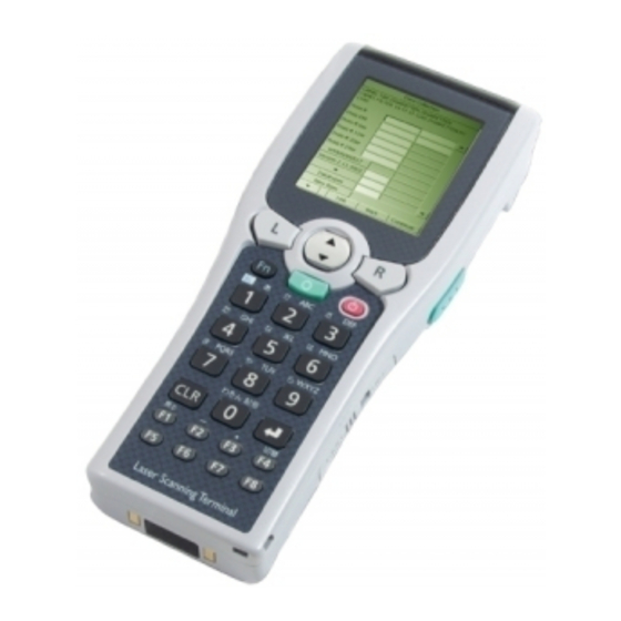
Preface A new industrial handheld terminal has been developed. CASIO introduces the DT-X5 series of handheld terminal with built-in SH-3 (32-bit RISC type) Processor, high speed laser scanner and diverse wireless LAN communications via Bluetooth as standard and IEEE802.11b WLAN (model dependent). Running under Microsoft Windows CE .NET4.1 operating system, the rugged DT-X5 is designed specifically for industrial... -
Page 6: Overview
1. Overview 1.1 Features Incorporates .NET technology • Uses WindowsCE .NET 4.1 operating system. • Makes effective use of .NET resources developed by other parties. • Employment of Embedded OS makes it possible to build a flexible WindowsCE system. Enhanced communicating functions •... -
Page 7: Available Models And Options
1.2 Available Models and Options Table 1.1 Models of DT-X5 series Wireless LAN Scan Engine Model Operating battery IEEE802.11b Bluetooth Laser C-MOS DT-X5M10E Lithium-ion/ Alkaline DT-X5M10R ETSI Lithium-ion DT-X5M30E Lithium-ion/ Alkaline DT-X5M30R ETSI Lithium-ion DT-X5M30U Lithium-ion/ Alkaline IEEE802.11b : WLAN module (compliant with IEEE802.11b) is integrated as standard. - Page 8 The accessories in the table below are accompanied as accessory in each individual carton box of DT-X5. Table 1.3 Accessory Product Q’ty Remark AA size Alkaline battery For DT-X5M10E, M30E and M30U only Alkaline battery holder For DT-X5M10E, M30E and M30U only Wrist strap Large-capacity battery pack cover For DT-5025LBAT...
-
Page 9: Options And Interfaces
1.2.1 Options And Interfaces DT-X5 IrDA Printer ( Recommended Option) IrDA Ver. 1.1 Bridge Basic Cradle HA-A60IO AC Adaptor AD-S42120AE RS-232C Bridge Satellite Cradle RS-422 RS-422 HA-A61IO AC Adaptor Bridge Satellite AD-S42120AE Cradle HA-A61IO Power Supply Cradle-type Battery Terminals Charger ( Built-in Battery HA-A30CHG Charge Circuit) -
Page 10: General Guide
Views for DT-X5M10E, DT-X5M10R Fig. 1.3 Note: The front view in Fig. 1.3 is for all the models of DT-X5 series. Views for side and back of DT-X5M30E, DT-X5M30U and DT-X5M30R Fig. 1.4 Refer to Table 1.4 “Names of parts” in the following page for each part and its description. - Page 11 Table 1.4 Names of parts Name Description Indicator 1 This indicator is green when charging is completed, and red during charging. Indicator 2 This indicator is green when the bar code has been read successfully, and red when a reading error has occurred. LCD panel Displays text, operating instructions and so forth.
-
Page 12: Ha-A34At Car Mounted Battery Charger
1.3.1 HA-A34AT Battery Charger Car Mount Unit View Power Indicator Lamp Power Contacts HA-A30CHG HA-A34AT Power Switch Car power code jack Remove button Fig. 1.5 Note: The view in Fig. 1.5 shows HA-A34AT (Battery Charger Car Mount Unit) with HA-A30CHG (Cradle-type Battery Charger) integrated to it. -
Page 13: Ha-A61Io, Ha-60Io Cradles
1.3.2 HA-A61IO and HA-A60IO Cradles Views Right Front Back Bottom Fig. 1.6 Refer to Table 1.5 “Names of parts” in the following page for each part name and its description. - Page 14 Table 1.5 Names of parts Part Name Description IR port This port transfers data with the terminal IR port non-contact communication. Terminal detect switch This switch detects when the terminal is not seated correctly on the Cradle. Power contacts Power is supplied to the terminal via these contacts. Fall protector This is a removal attachment that prevents the terminal from tipping over and falling.
-
Page 15: Dt-5022Chg Dual Battery Charger
1.3.3 DT-5022CHG Dual Battery Charger Views Charge status indicators Battery pack compartments Dual charger connection terminals Right Left AC adaptor jack Bottom Connection attachments Fig. 1.7... -
Page 16: Ha-A20Bat, Dt-5025Lbat Battery Packs
1.3.4 HA-A20BAT and DT-5025LBAT Battery Packs Views HA-A20BAT DT-5025LBAT Left Left Side Side Charge/Power supply Charge/Power terminals supply terminals Bottom Bottom Fig. 1.8... -
Page 17: Hardware Specifications
2. Hardware Specifications 2.1 DT-X5 Table 2.1 Item Specification Remark CPU, Memory SH3 (32-bit RISC type) Operating system Microsoft® Windows® CE .NET Ver. 4.1 16 MB (user area: approx. 7.5 MB) FROM (OS) 32 MB FROM (Storage) 32 MB (user area: approx. 30 MB) Laser scanner Method Semi-conductor laser... - Page 18 Input Keyboard Cursor up-and-down key, L and R keys, Ten keys (0 to 9), Fn key, Multi key, Function keys (F1 to F8) Control keys Power key, Reset switch Trigger keys 2 pcs (on the left and right sides) IrDA Standard IrDA Version 1.1 Method...
- Page 19 Lithium-ion battery HA-A20BAT : Approx. 5 hours Conditions; pack charge time DT-5025LBAT : Approx. 10 hours - The power switch is turned off. - The lithium-ion battery pack is a brand new. - The surrounding temperature is at room temperature. Memory backup battery Approx.
- Page 20 Table 2.2 Operating hours by model WLAN Scan Operating Model Battery Operating mode IEEE802.11b engine hour Alkaline batteries Approx. 200 Scanning 2 times per 10 seconds. DT-X5M10E Laser HA-A20BAT Approx. 90 DT-5025LBAT Approx. 180 HA-A20BAT Approx. 90 Scanning 2 times per 10 seconds DT-5025LBAT Approx.
- Page 21 Table 2.4 Readable 2D stacked code symbologies C-MOS Laser Symbology Output format/Append function imager scanner Code49 PDF417 MicroPDF Codablock F EAN8/13 Composite RSS Composite UCC/EAN128 Composite TLC39 RSS-14 (Stacked type) Stacked/ Stacked Omnidirectional RSS Expanded (Stacked type) Stacked...
-
Page 22: Reference For Laser Scanner Performance
2.1.1 Reference for Laser Scanner Performance Reference of the laser scanner performances below for the DT-X5M10E/DT-X5M10R is provided as a guide to be utilized by the user. The user can refer to these reference values in the table for his or her specific business application. - Page 23 (Unit: mm) 44 44 44 44 44 44 0 to50 0 to 60 0 to 150 0.25 Resolution 0 to 200 0.33 0 to 300 0 to 400 Fig. 2.1...
-
Page 24: Reference For C-Mos Imager Performance
2.1.2 Reference for C-MOS Imager Performance Reference of the C-MOS imager performances below for the DT-X5M30E, DT-X5M30R and DT-X5M30U is provided as a guide to be utilized by the user. The user can refer to these reference values in the table for his or her specific business application. - Page 25 Basic scanning conditions: Test chart : Dedicated test pattern (1D, 2D Stacked) Resolution : 1D 0.25 mm / 2D 0.5 mm : 0.9 or greater Read judgment : 7 times per 10 scans First Decode Depth : 110 mm from the LED emission port Pitch angle : α...
-
Page 26: Ha-A61Io, Ha-A61Io
2.2 HA-A60IO, HA-A61IO Table. 2.7 Item Specification Remark Interface Standard IrDA Ver. 1.1 compatible Comm. method Half duplex IrDA Synchronization Start/stop method Comm. speed 4 Mbps (maximum) Standard USB Ver. 1.1 compatible Comm. speed 12 Mbps (maximum) 1. VBus 2. –Data (D-) 3. - Page 27 The illustration of the power contact on the left is viewed Power contact at the front of the Power contact cradle. Weight/Dimensions Table 2.8 Model no. Configuration Specification Weight In desktop state Approx. 530 g In wall mount state Approx. 620 g HA-A61IO Dimensions In desktop state...
-
Page 28: Ha-A34At
2.3 HA-A34AT Table 2.9 Item Specification Remark No. of LEDs No. of display colors In red and green Display content Power status (“POWER”) Display Status LED Indicates the status of terminal being mounted on the charger. : Power is off. Flashing in green : Power is on and the terminal is mounted on the charger. -
Page 29: Ha-A30Chg
2.4 HA-A30CHG Table 2.11 Item Specification Remark No. of LEDs Display Status LED No. of display colors In red and green Display content Power status (“POWER”) Input Detection switch for DT-X5 Push switch Input voltage DC 12V±5% Consumption current Approx. 3.5A While supplying Input from AC power or... -
Page 30: Dip Switch Setting For Ha-A61Io
2.5 DIP Switch Setting for HA-A61IO The DIP switch is located on the rear side of the Bridge Satellite Cradle. Change the ON/OFF settings according to your required system configuration. The new settings do not go into effect until the power switch is turned off and then back on again. -
Page 31: Status Indication With Leds
2.6 Status Indications with LEDs Various operational statuses on the HA-A61IO can be displayed using the LEDs. The following table describes LED modes and their meanings. Table 2.13 Item Specification Remark Power status indicator Power off. 2-color LED (POWER) Power is on and the terminal is mounted correctly. Green Power is on but the terminal is not mounted correctly. -
Page 32: Dt-5022Chg
2.7 DT-5022CHG Basic Block Table 2.14 Item Specification Remark Basic function Rechargeable battery pack HA-A20BAT Battery pack (1,700 mAH) Dedicated batteries only. DT-5025LBAT Large-capacity size battery pack (3,400 mAH) AC adaptor AD-S45150AU Input; 100 to 230VAC With US power cord AD-S45150AE Input;... - Page 33 Battery Charge Block Table 2.17 Item Specification Remark Charge control Output voltage DC4.22V±30mV Charge current (standard mode) DC1,600mA±10% Charge current (standby mode) DC160±40mA Full charge detection current DC120±30mA Voltage control Full charge detection voltage 4.1V Re-charge detection voltage 4.0V Re-charge detection voltage DC4.0±0.1V Input voltage DC8.0 to 20V...
-
Page 34: Ha-A20Bat, Dt-5025Lbat
2.8 HA-A20BAT, DT-5025LBAT Table 2.19 Specification Item Remark HA-A20BAT DT-5025LBAT Rated capacity 1,700 mAH 3,400 mAH 0.2C discharge Rated voltage 3.7V 3.7V 0.2C discharge Discharge end voltage 2.75V 2.75V Standard charge current 1.0 CA (=1.55A) 1.6A 0 to 40 °C 0 to 50 °C Charge voltage 4.2±0.05V... -
Page 35: Product Identification And Reference Numbers
3. Product Identification and Reference Numbers On the back of the terminal and its options (major options only), there is a bar code and numbers printed on label as shown in Fig. 3.1 below. This bar code is represented by 15 digits of Code128 and by alphanumeric characters beneath the bar code. The numbers from 1 to 9 in the figure represent identification and references of the terminal. -
Page 36: Quality References
4. Quality References This chapter describes about references of the DT-X5 and its dedicated options concerned with environmental performance, compliance, mechanical and electric durability, etc. 4.1 Environmental Performances 4.1.1 DT-X5 Table 4.1 Item Specification Condition Temperature Operation -20 ºC to 50 ºC 0 to 40 ºC while mounting on Cradle. -
Page 37: Ha-A61Io, Ha-A30Chg
4.1.2 HA-A60IO, HA-A61IO, HA-A30CHG Table 4.2 Item Specification Condition Temperature Operation 0 ºC to 40 ºC Storage -10 ºC to 50 ºC Humidity Operation 30% to 80%RH (No condensation) Storage 30% to 90%RH (No condensation) Storage in carton box Temperature -10 ºC to 50 ºC Humidity 30% to 90%RH... -
Page 38: Ha-A34At
4.1.3 HA-A34AT Table 4.3 Item Specification Condition Temperature Operation 0 ºC to 40 ºC Storage -40 ºC to 85 ºC Humidity Operation 30% to 80%RH (No condensation) Storage 30% to 95%RH (No condensation) Storage in carton box Temperature -10 ºC to 50 ºC Humidity 30% to 90%RH 4.1.4 DT-5022CHG... -
Page 39: Electric Performances
4.2 Electrical Performances 4.2.1 DT-X5 Table 4.6 Item Specification Remark DC1.1A/3.0V to 5V For DT-X5M10E DC1.3A/3.0V to 5V For DT-X5M30E/DT-X5M30U Power consumption DC1.4A/3.7V to 5V For DT-X5M10R DC1.6A/3.7V to 5V For DT-X5M30R Anti-static strength ±4 KV (contact), ±8 KV (in air) Malfunction Compliant with EN6100-4-2 ±12 KV... -
Page 40: Dt-5022Chg
4.2.4 DT-5022CHG Table 4.9 Item Specification Remark Anti-static strength ESD method: 250 pF, 100 ohm Probe: Finger type Malfunction ±5 KV Polarity: ± Destruction ±10 KV 4.2.5 HA-A20BAT, DT-5025LBAT Table 4.10 Item Specification Remark Anti-static strength ESD method: 250 pF, 100 ohm Malfunction ±5 KV Probe: Finger type... -
Page 41: Mechanical Performances
4.3 Mechanical Performances 4.3.1 DT-X5 Table 4.11 Item Specification Condition Resistance to drop impact (height) In bare condition 180 cm Onto concrete, one time on each of the 6 sides and 4 corners. In individual carton box 70 cm or less Onto concrete, one time on each of the 6 sides, 1 corner, 3 edges. -
Page 42: Ha-A20Bat, Dt-5025Lbat
4.3.4 HA-A20BAT, DT-5025LBAT Table 4.14 Item Specification Condition Resistance to vibration 1.5 G or less 10 to 55 Hz In X,Y, and Z directions Reciprocally for 30 minutes Resistance to impact In bare condition 100 cm 6 faces, 4 edges onto P-tile. In individual carton box 70 cm or less 6 faces, 3 edges, 1 corner onto P-tile. -
Page 43: Reliability
4.4 Reliability 4.4.1 DT-X5 Table 4.15 Item Specification Remark/Condition Service life Backlight 10,000 hours At half-life period Laser scanner 10,000 hours C-MOS imager 70,000 hours Trigger keys 1,000,000 times For each trigger key Other keys 500,000 times Mounting/removing of the 10,000 times terminal to/from the Cradle MTBF... -
Page 44: Compliance
4.5 Compliance 4.5.1 DT-X5 EMC, EMI, Safety, WLAN /Bluetooth type approvals Table 4.18 Compliance Standard Europe EN301.489-17 EN60950 EN60825 EN300.328-2 EN50371 Model (EMI,EMS) (Safety) (Laser) (Bluetooth, EN50361 WLAN) EN50360 (SAR) DT-X5M10E DT-X5M10R DT-X5M30E DT-X5M30R Columns in gray color: not applicable. Table 4.19 Compliance Standard Model... -
Page 45: Chapter 5 Cable Specifications
5. Cable Specifications 5.1 For Chain Connection and Short Length Length; 1 meter or less M a x m im u m View from side View from top 1 2 3 4 5 6 1 2 3 4 5 6 C a b le ( s e e T a b le 5 . -
Page 46: For Chain Connection And Long Length
5.2 For Chain Connection and Long Length Length; 1 meter or longer View from side Max. 1,000m View from top 1 2 3 4 5 6 1 2 3 4 5 6 Modular plug compatible Cable compatible with SK-UTP with 6/6-6 FR SYK50 by 100M3P by Sanyo Industrial Co. -
Page 47: Chapter 6 Precautions
6. Precautions 6.1 Handling Precautions Precautions for short-term storage (1 to 2 days) • If the DT-X5 is to be stored over holidays (including Saturday and Sunday), replace the battery pack (or AA-size alkaline batteries) with brand-new one before starting the holiday. This will conserve the built-in memory backup battery and ensure retention of data on the terminal. -
Page 48: Safety
When charging the battery pack use only dedicated cradles or dedicated battery charger and its AC adaptor available from CASIO, at a temperature between 0°C and 40°C. If the battery pack is charged with battery chargers other than those specified by CASIO, it may be over-charged, or charged with an excessive current, or have abnormal chemical reactions induced, causing it to become hot, smoke, explode, or ignite. -
Page 49: General
If the DT-X5 is continuously used in an abnormal condition, a fire or electric shock may occur. If there is an abnormality, immediately turn off the Power switch, and be sure to remove the batteries and then contact a CASIO distributor for repair. •... - Page 50 • Avoid exposing it to water and foreign matter Should foreign matter (metal chips, water, liquid chemicals) enter inside the product, immediately turn off the DT-X5, remove the battery pack, and then contact a CASIO distributor. • Memory protection Contents of the DT-X5 should always be backed up in personal computer to make a separate record from that on the terminal.
Need help?
Do you have a question about the DT-X5 Series and is the answer not in the manual?
Questions and answers