Table of Contents
Advertisement
AC Servo Drives
Σ-V Series
USER'S MANUAL
Universal Feedback Module Type 3
Model: SGDV-OFB03A
To properly use the product, read this manual thoroughly
and retain for easy reference, inspection and maintenance.
Ensure the end user receives this manual.
Please check www.yaskawa.eu.com for up-to-date versions.
MANUAL NO. YEU SIEP C720829 24A
Set-up Procedure for Fully-closed Loop Control
Set-up Procedure for Semi-closed Loop Control
SERVOPACK with Semi-closed Loop Control for Rotary Motors
SERVOPACK with Semi-closed Loop Control for Linear Motors
Checking Products
Specifications
Hardware Installation
Applicable Scope
Encoder Interfaces
Hall Sensor Signals Interface
Motor and Scale Parameter File
Error Lists
1
2
3
4
5
6
7
8
9
10
11
12
Advertisement
Table of Contents

Subscribe to Our Youtube Channel
Related Manuals for YASKAWA S-V Seres


Summary of Contents for YASKAWA S-V Seres
- Page 1 Set-up Procedure for Semi-closed Loop Control Motor and Scale Parameter File SERVOPACK with Semi-closed Loop Control for Rotary Motors SERVOPACK with Semi-closed Loop Control for Linear Motors Error Lists Please check www.yaskawa.eu.com for up-to-date versions. MANUAL NO. YEU SIEP C720829 24A...
- Page 2 Yas- kawa. No patent liability is assumed with respect to the use of the information contained herein. Moreover, because Yaskawa is constantly striving to improve its high-quality products, the information contained in this manual is subject to change without notice.
- Page 3 About this Manual This manual describes informations required for designing and maintaining the Universal Feedback Option Module for Σ-V series SERVOPACKs. The Feedback module is available in different versions. Type 3 of the module supports encoders with A quad B (described in this manual). Be sure to refer to this manual and perform design and maintenance to select devices correctly.
- Page 4 • Parameter Notation The following two types of notations are used for parameter digit places and settings. Example Notation Example for Pn000 Pn000 Digit Notation Set Value Notation Meaning Notation Method Notation Method Meaning Indicates that digit 1 of the Pn000.0 = x Indicates digit 1 Digit 1...
- Page 5 Selecting Trial Maintenance Models and Ratings and Panels and Trial Operation Name Peripheral Specifications Wiring Operation and Servo Inspection Devices Adjustment Σ-V Series User’s Manual Operation of Digital Operator (SIEP S800000 55) Σ-V Series User's Manual Design and Maintenance Rotational Motor ...
- Page 6 Safety Information The following conventions are used to indicate precautions in this manual. Failure to heed precautions pro- vided in this manual can result in serious or possibly even fatal injury or damage to the products or to related equipment and systems.
- Page 7 Safety Precautions These safety precautions are very important. Read them before performing any procedures such as checking products on delivery, storage and transportation, installation, wiring, operation and inspection, or disposal. Be sure to always observe these precautions thoroughly. WARNING • Never touch any rotating motor parts while the motor is running. Failure to observe this warning may result in injury.
- Page 8 Storage and Transportation CAUTION • Do not store or install the product in the following locations. Failure to observe this caution may result in fire, electric shock, or damage to the product. • Locations subject to direct sunlight • Locations subject to ambient operating temperatures outside the range specified in the storage/installation temperature conditions •...
- Page 9 Wiring CAUTION • Be sure to wire correctly and securely. Failure to observe this caution may result in motor overrun, injury, or malfunction. • Do not connect a commercial power supply to the U, V, or W terminals for the servomotor connec- tion.
- Page 10 Operation CAUTION • Always use the servomotor and SERVOPACK in one of the specified combinations. Failure to observe this caution so may result in fire or malfunction. • Conduct trial operation on the servomotor alone with the motor shaft disconnected from the machine to avoid accidents.
- Page 11 • The drawings presented in this manual are typical examples and may not match the product you received. • If the manual must be ordered due to loss or damage, inform your nearest Yaskawa representative or one of the offices listed on the back of this manual.
- Page 12 6. Events for which Yaskawa is not responsible, such as natural or human-made disasters (2) Limitations of Liability 1. Yaskawa shall in no event be responsible for any damage or loss of opportunity to the customer that arises due to failure of the delivered product.
- Page 13 Applicable Standards North American Safety Standards (UL) Standards Model (UL File No.) SERVOPACK • SGDV UL508C (E147823) • SGMJV • SGMAV Servomotor • SGMEV UL1004 (E165827) • SGMGV • SGMSV Underwriters Laboratories Inc. Note: Applicable when the Feedback Option Module is attached to the SERVOPACKs for the command option attachable type.
-
Page 14: Table Of Contents
CONTENTS Chapter 1 Checking Products ........1-1 1.1 Checking Products on Delivery . - Page 15 Chapter 8 Set-up Procedure for Semi-closed Loop Control ... .8-1 8.1 Safety Precautions..........8-2 8.2 Setup Procedure .
-
Page 17: Chapter 1 Checking Products
Checking Products This chapter describes how to check products upon delivery. 1.1 Checking Products on Delivery ....... . . 1-2 1.2 Nameplate and Model Designation . -
Page 18: Checking Products On Delivery
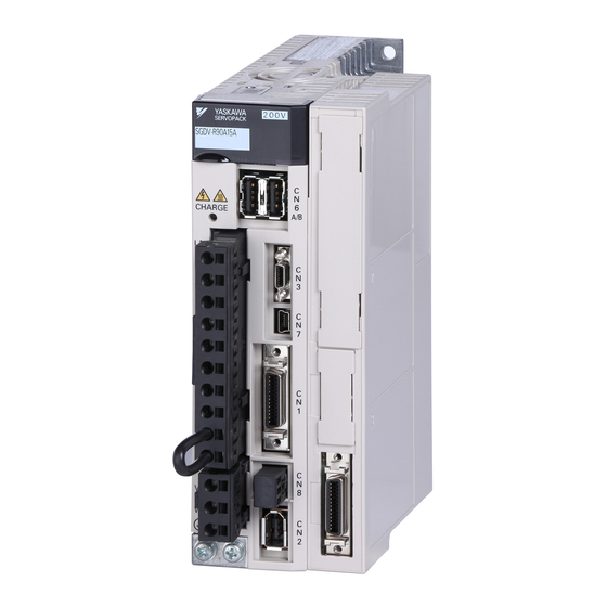
Check the nameplate to confirm that the Module that is mounted is the Universal Feedback Module. The nameplate is located in the following position. Nameplate and Model Designation Nameplate Example Application Module model number Name OPTION MODULE MODEL SGDV-OFB03A 0/N 123456-1-1 S/N 123456789ABCDEF SGDV YASKAWA EUROPE GMBH MADE IN JAPAN Manufacturing number Nameplate... - Page 19 1.2 Nameplate and Model Designation Model Designation SGDV – OF B03 A 6th digit: Design Revision Order Series SGDV Σ-V Series 3rd + 4th + 5th digits: Interface Specifications Code Interface 1st + 2nd digits: Module Type Code Module Pulse A quad B Encoders Feedback type option module ...
-
Page 20: Nameplate Location
1 Checking Products Nameplate Location OFB03A Nameplate (Model no.) Nameplate (Ratings) -
Page 21: Chapter 2 Specifications
Specifications This chapter gives an overview and describes the specifications of the Universal Feedback Option Module. 2.1 Overview ..........2-2 2.2 Specifications of the Universal Feedback Option Module . -
Page 22: Overview
2 Specifications 2.2.1 General Specifications Overview The Σ-V series Universal Feedback Option Module SGDV-OFB03A supports encoders with A quad B. The feedback option module consists of option card and option case unit. It can be installed to all the types of Sigma-5 SERVOPACKs. -
Page 23: Chapter 3 Hardware Installation
Hardware Installation This chapter describes the hardware installation of the Universal Feedback Option Module. 3.1 Mounting the Universal Feedback module ......3-2... -
Page 24: Mounting The Universal Feedback Module
3 Hardware Installation Mounting the Universal Feedback module The Universal Feedback module will be mounted on the right side of the Sigma-V servopack. To mount the network module to the SERVOPACK follow the instructions below. 1. Fit the mounting plate (F) into the recess on the SERVOPACK, and fix the plate with the mounting screws (G). - Page 25 3.1 Mounting the Universal Feedback module 4. Fix the board on the SERVOPACK with three screws. (Tightening torque: 0.14 Nm) B -Mounting Screws Tighten this pre-attached screw as well. 5. Align the front end of the module cover (H) with the front panel of the SERVOPACK as shown in the illustra- tion, and place the module cover so that you can view the installed board from the opening (where the front cover is removed) on the module cover.
- Page 26 3 Hardware Installation 7. Now snap on the cover for the network module to the servo amplifier, the completed unit will look like the following picture.
-
Page 27: Chapter 4 Applicable Scope
Applicable Scope This chapter describes the application fields of the Universal Feedback Option Module. 4.1 SERVOPACK for Rotary and Linear Motors ..... . . 4-2 4.2 SERVOPACK with Semi-closed Loop Control . -
Page 28: Servopack For Rotary And Linear Motors
Motor parameter file needs to be pre- A quad B pulse with SGDV-OFB03A Party pared by YASKAWA SERVOPACK for Rotary and Linear Motors Feature This system is for driving the Sigma-1 servo motors or third party servo motors. Parameter Setting Pn002.3=0, Pn00B.3=1... -
Page 29: Servopack With Semi-Closed Loop Control
A quad B pulse with SGDV-OFB03A Party pared by YASKAWA SERVOPACK with Semi-closed Loop Control Feature This system is for driving YASKAWA linear motors or third party linear motors. Parameter Setting Pn002.3=0, Pn00B.3=1 Description Sigma-5 • YASKAWA linear motor SERVOPACK •... -
Page 30: Servopack With Fully-Closed Loop Control
4 Applicable Scope SERVOPACK with Fully-closed Loop Control Motor Scale Interface Available solutions Remarks YASKAWA Serial with SGDV-OFA01A with SGDV-OFA01A and YASKAWA Sine and Cosine with JZDP--000-E A quad B pulse with SGDV-OFB03A Retrofit to Sigma-2 SERVOPACK with Fully-closed Loop Control... -
Page 31: A Quad B Pulse Interface
Encoder Interfaces This chapter describes the encoder interfaces of the Universal Feedback Option Module. 5.1 A quad B Pulse interface ........5-2 5.1.1 Overview . -
Page 32: A Quad B Pulse Interface
5 Encoder Interfaces 5.1.1 Overview A quad B Pulse interface 5.1.1 Overview A quad B pulse signals is counted by each edges in the master. The interface block diagram is shown below. Encoder Master Servo Serial A quad B FPGA Pulse encoder 5.1.2... -
Page 33: Chapter 6 Hall Sensor Signals Interface
Hall Sensor Signals Interface This chapter describes the hall sensor signals interface of the Universal Feedback Option Module. 6.1 Overview ..........6-2 6.1.1 Technical Data . -
Page 34: Overview
6 Hall Sensor Signals Interface 6.1.1 Technical Data Overview Hall sensor signals provided by some sensor devices are used as easier recognition for motor pole position. With hall sensor signals, the detecting function implemented on Sigma-5 is not required. Used sensor devices must output each U/V/W hall sensor signals. - Page 35 Set-up Procedure for Fully-closed Loop Control This chapter describes the set-up procedure for fully-closed loop control of the Universal Feedback Option Module. 7.1 Safety Precautions ......... . . 7-2 7.2 Set-up Procedure .
-
Page 36: Chapter 7 Set-Up Procedure For Fully-Closed Loop Control
7 Set-up Procedure for Fully-closed Loop Control Safety Precautions These set-ups shall be done in accordance with described procedures. And, they shall be done when the system configurations and components are changed. Failure to do so may result not only in faulty operation and damage to equipment, but also in personal injury. Set-up Procedure Follow the procedures and instructions provided in this manual and the following user’s manuals for trial operation:... -
Page 37: Feedback Option Module Set-Up For Fully-Closed Loop Control
USB cable Scale parameter file Write scale parameters into the feedback option module via SGDV SERVOPACK YASKAWA Motor Linear Scale Note: This feature is available in SigmaWin+ Version 5.6.1 and later. (1) Set-up Procedure for Encoder File Install a motor, scale and SERVOPACK. - Page 38 7 Set-up Procedure for Fully-closed Loop Control 7.2.1 Feedback Option Module Set-up for Fully-closed Loop Control For Fully-closed Loop operation, the parameters have to be set as follows: Pn002.3 = 1 or 3 Pn00B.3 = 0 (2) Write Parameters using SigmaWin+ In SigmaWin+ select “Setup >...
- Page 39 7.2 Set-up Procedure Click “Ref.” to open the motor parameter file. Select the parameter file provided by YASKAWA and click “Open”. The scale parameter file information is displayed. Make sure that the scale parameter file information of the installed encoder is displayed.
- Page 40 7 Set-up Procedure for Fully-closed Loop Control 7.2.1 Feedback Option Module Set-up for Fully-closed Loop Control If all scale parameter file information is correct, click “Write” to start writing the scale parameters. If the scale parameter file information is not correct, click “Back” to select another scale parameter file or click “Cancel”...
- Page 41 7.2 Set-up Procedure Note: If a feedback option card is not connected, the following message will appear. - FBOpMotID - Not available Even if a feedback option card is connected, the following message will appear if the option card contains no motor data or encoder data.
-
Page 42: Sigma-5 Servopack Set-Up For Fully-Closed Loop Control
7 Set-up Procedure for Fully-closed Loop Control 7.2.2 Sigma-5 SERVOPACK Set-up for Fully-Closed Loop Control 7.2.2 Sigma-5 SERVOPACK Set-up for Fully-Closed Loop Control According to applications, these parameters should be set for the correct operation of Sigma-5 with the option modules. -
Page 43: Servopack For Fully-Closed Loop Control
7.3 SERVOPACK for Fully-closed Loop Control SERVOPACK for Fully-closed Loop Control 7.3.1 Rotation/Movement Direction The relationship between motor feedback direction and external feedback direction is dependent on the mounted conditions. So, the parameters below are used for the coordination. Parameter Function Default Value When enabled... -
Page 44: External Encoder Resolution To Motor Feedback
7 Set-up Procedure for Fully-closed Loop Control 7.3.2 External Encoder Resolution to Motor Feedback 7.3.2 External Encoder Resolution to Motor Feedback The relationship between motor feedback position and external feedback position is dependent on the mounted encoder specifications. So, the parameter below is used for the coordination. This parameter indi- cates the number of external encoder period per motor rotation. - Page 45 Set-up Procedure for Semi-closed Loop Control This chapter describes the setup procedure for semi-closed loop control of the Universal Feedback Option Module. 8.1 Safety Precautions ......... . . 8-2 8.2 Setup Procedure .
-
Page 46: Safety Precautions
8 Set-up Procedure for Semi-closed Loop Control Safety Precautions These set-ups shall be done in accordance with described procedures. And, they shall be done when the system configurations and components are changed. Failure to do so may result not only in faulty operation and damage to equipment, but also in personal injury. Setup Procedure Follow the procedures and instructions provided in this manual and the following user’s manuals for trial operation:... -
Page 47: Feedback Option Module Set-Up
Note: This feature is available in SigmaWin+ Version 5.6.1 and later. (1) Set-up Procedure Install a motor, scale and SERVOPACK. Request the motor parameter file of the installed motor from YASKAWA Europe GmbH. In SigmaWin+ select “Parameters > Parameter edit”. Set parameter Pn00B.3 = 1. - Page 48 8 Set-up Procedure for Semi-closed Loop Control 8.2.1 Feedback Option Module Set-up For Semi-closed Loop operation, the parameters have to be set as follows: Pn002.3 = 1 Pn00B.3 = 1 (2) Write Parameters using SigmaWin+ In SigmaWin+ select “Setup > Motor parameter scale write”. If you are sure the settings suit the connected motor, confirm the warning with “OK”.
- Page 49 8.2 Setup Procedure Click “Ref.” to open the motor parameter file. Select the parameter file provided by YASKAWA and click “Open”. The motor parameter file information is displayed. Make sure that the motor parameter file information of the installed motor is displayed.
- Page 50 8 Set-up Procedure for Semi-closed Loop Control 8.2.1 Feedback Option Module Set-up If all motor parameter file information is correct, click “Write” to start writing the motor parameters. If the motor parameter file information is not correct, click “Back” to select another motor parameter file or click “Cancel”...
- Page 51 8.2 Setup Procedure (3) Precautions If the scale parameters have not been written in the module, A.CA0 (Encoder Parameter Error) will occur when the power in turned ON. Monitor the scale data using the monitoring function to see if the scale parame- ters are saved in the module.
- Page 52 8 Set-up Procedure for Semi-closed Loop Control 8.2.1 Feedback Option Module Set-up Even if a feedback option card is connected, the following message will appear if the option card contains no motor data or encoder data. - FBOpMotID - Not available •...
-
Page 53: Sigma-5 Servopack Set-Up With Rotary Motor
8.2 Setup Procedure 8.2.2 Sigma-5 SERVOPACK Set-up with Rotary Motor According to applications, these parameters should be set for the correct operation of Sigma-5 with the option modules. Parameter Default Required Function Cat. When enabled Value value Dig. Pn000 Basic Function Select Switch 0 Direction Selection Forward command for forward direction After restart... -
Page 54: Sigma-5 Servopack Set-Up With Linear Motor
8 Set-up Procedure for Semi-closed Loop Control 8.2.3 Sigma-5 SERVOPACK Set-up with Linear Motor Parameter Default Required Function Cat. When enabled Value value Dig. Polarity Detection Speed Loop Integral Time Pn482 30.00 Immediately [0.01 msec] Polarity Detection Command Accel/Decel Time Pn486 Immediately [msec]... - Page 55 8.2 Setup Procedure Parameter Default Required Function Cat. When enabled Value value Dig. Pn080 Application Function Select Switch B Hall Sensor Selection Enables hall sensor After restart Disables hall sensor Motor Phase Selection Sets positive position feedback as phase sequence of U, V, W After restart Sets negative position feedback as phase sequence of U, V, W...
- Page 56 8 Set-up Procedure for Semi-closed Loop Control 8.2.3 Sigma-5 SERVOPACK Set-up with Linear Motor 8-12...
-
Page 57: Motor And Scale Parameter File Requirements For Servopacks For Rotary
Motor and Scale Parameter File This chapter describes the motor and scale parameter file for rotary and linear motors of the Universal Feedback Option Module. 9.1 Motor and Scale Parameter File Requirements for SERVOPACKs for Rotary Motors ........... . 9-2 9.1.1 Motor Parameters . -
Page 58: Motor Parameters
SERVOPACKs for Rotary Motors If a 3rd party motor shall be operated, then a motor parameter file has to be created by Yaskawa. To cre- ate this file, provide Yaskawa with the following information: motor data and a sample motor for check- ing the overload characteristics. -
Page 59: Scale Parameters
9.1 Motor and Scale Parameter File Requirements for SERVOPACKs for Rotary Motors Overload Detection Torque 2 Base Torque for Overload Protection Overload Detection A720 A710 Overload Detection Torque 1 1000 Overload Detection Time 1 Overload Detection Time 2 100 120 140 160 180 200 220 240 260 280 300 320 Torque [%] 9.1.2 Scale Parameters Description... -
Page 60: Motor And Scale Parameter File Requirements For Servopacks For Linear
SERVOPACKs for Linear Motors If a 3rd party motor shall be operated, then a motor parameter file has to be created by Yaskawa. To cre- ate this file, provide Yaskawa with the following information: motor data and a sample motor for check- ing the overload characteristics. -
Page 61: Scale Parameters
9.2 Motor and Scale Parameter File Requirements for SERVOPACKs for Linear Motors Overload Detection Torque 2 Base Torque for Overload Protection Overload Detection A720 A710 Overload Detection Torque 1 1000 Overload Detection Time 1 Overload Detection Time 2 100 120 140 160 180 200 220 240 260 280 300 320 Torque [%] 9.2.2 Scale Parameters Description... - Page 62 9 Motor and Scale Parameter File 9.2.2 Scale Parameters...
- Page 63 SERVOPACK with Semi-closed Loop Control for Rotary Motors This chapter describes the rotary drives common in semi-closed loop. 10.1 Magnetic Pole ..........10-2 10.2 Motor Rotation Direction .
-
Page 64: Magnetic Pole
10 SERVOPACK with Semi-closed Loop Control for Rotary Motors 10.1 Magnetic Pole For driving third party motors and some Sigma-1 motors, the magnetic pole should be coordinated. The parameters in the following table are used for that. Parameter Function Default Value When enabled Dig. -
Page 65: Motor Rotation Direction
10.2 Motor Rotation Direction 10.2 Motor Rotation Direction The relationship between feedback position and motor magnetic pole position is dependent on the mounted conditions. So, the parameters below are used for the coordination. Parameter Function Default Value When enabled Dig. Pn000 Application Function Select Switch 0 Direction Selection... -
Page 66: Pole Detection Functionality
10 SERVOPACK with Semi-closed Loop Control for Rotary Motors 10.3 Pole Detection Functionality When using a rotary motor without hall sensor (except Sigma-1 motors), the pole detection should be exe- cuted. Make sure the following conditions are satisfied when executing the function. There is no danger when the rotary motor moves approximately 1/4 turn. - Page 67 10.3 Pole Detection Functionality After the function has been completed the motor power will turn OFF and the Servo Ready signal will turn ON. Then the function cannot be executed even if the /P-DET signal is turned ON and OFF. Then the control power is restored, the function must be executed again.
-
Page 68: Servopack For Rotary Motors
10 SERVOPACK with Semi-closed Loop Control for Rotary Motors 10.4.1 Encoder Pulse Output 10.4 SERVOPACK for Rotary Motors 10.4.1 Encoder Pulse Output These parameters are used for position counting by upper controller. Sigma-5 SERVOPACK outputs the pulse according to the settings. If the application does not use this encoder pulse output (e.g. network application), the functionality can be disabled by the parameter Pn081.1 = 1 Note: This specification is applied to the usage with the encoder feedback. - Page 69 SERVOPACK with Semi-closed Loop Control for Linear Motors This chapter describes the linear drives common in semi-closed loop. 11.1 Magnetic Pole ..........11-2 11.2 Motor Rotation Direction .
-
Page 70: Magnetic Pole
11 SERVOPACK with Semi-closed Loop Control for Linear Motors 11.1 Magnetic Pole For driving linear motors, the magnetic pole should be coordinated. The parameters in the following table are used for that. Parameter Function Default Value When enabled Dig. Pn080 Application Function Select Switch 80 Hall Sensor Selection Enables hall sensor... -
Page 71: Motor Rotation Direction
11.2 Motor Rotation Direction 11.2 Motor Rotation Direction The relationship between feedback position and motor magnetic pole position is dependent on the mounted conditions. So, the parameters below are used for the coordination. Parameter Function Default Value When enabled Dig. Pn000 Application Function Select Switch 0 Direction Selection... -
Page 72: Pole Detection Functionality
11 SERVOPACK with Semi-closed Loop Control for Linear Motors 11.3 Pole Detection Functionality When using a linear motor without pole sensor, the pole detection should be executed. Make sure the follow- ing conditions are satisfied when executing the function. There is no danger when the linear motor moves approximately 10 mm. In case the function fails, the linear motor may move approximately 50 mm. - Page 73 11.3 Pole Detection Functionality • When using different timing for the execution of the function and sending the Servo ION signal. After the function has been completed the motor power will turn OFF and the Servo Ready signal will turn ON.
-
Page 74: Servopack For Linear Motors
11 SERVOPACK with Semi-closed Loop Control for Linear Motors 11.4.1 Encoder Pulse Output 11.4 SERVOPACK for Linear Motors 11.4.1 Encoder Pulse Output These parameters are used for position counting by upper controller. Sigma-5 SERVOPACK outputs the pulse according to the settings. If the application does not use this encoder pulse output (e.g. network application), the functionality can be disabled by the parameter Pn081.1 = 1 Note: C-pulse synchronizes to the edge of A/B-pulse. - Page 75 Error Lists This chapter describes the error lists of the Universal Feedback Option Module. In the combination with this option module, Sigma-5 SERVOPACK can detect the alarms shown as below. For error handling, refer to Sigma-5 SERVOPACK user’s manual. 12.1 Errors related to Feedback Option Module Identification ... . 12-2 12.2 Errors in Fully-closed Loop Control .
-
Page 76: Chapter 12 Error Lists
12 Error Lists 12.1 Errors related to Feedback Option Module Identification Alarm Number: Alarm Name (Alarm Cause Investigative Actions Corrective Actions Description) A.044: The setting of option The connected option module and the Semi-closed/Fully- Check the settings of module must be compati- setting value of Pn00B.3 and/or PN00B.3 and/or Pn002.3 ble with the settings of... -
Page 77: Errors In Fully-Closed Loop Control
12.2 Errors in Fully-closed Loop Control 12.2 Errors in Fully-closed Loop Control Alarm Number: Alarm Name (Alarm Cause Investigative Actions Corrective Actions Description) A.041: The encoder output pulse (Pn212) is Check the parameter Set Pn212 to a correct out of the setting range and does not Encoder Output Pulse Pn212. -
Page 78: Errors In Semi-Closed Loop Control With Rotary Motors
12 Error Lists 12.3 Errors in Semi-closed Loop Control with Rotary Motors Alarm Number: Alarm Name (Alarm Cause Investigative Actions Corrective Actions Description) A.041: The encoder output pulse (Pn212) is Check the parameter Set Pn212 to a correct Encoder Output Pulse out of the setting range and does not Pn212. - Page 79 12.3 Errors in Semi-closed Loop Control with Rotary Motors Alarm Number: Alarm Name (Alarm Cause Investigative Actions Corrective Actions Description) The noise interference occurred on Confirm that there is no the input/output signal line because problem with the encoder A.C91: the encoder cable is bent and the Check the encoder cable, cable layout.
-
Page 80: Errors In Semi-Closed Loop Control With Linear Motors
12 Error Lists 12.4 Errors in Semi-closed Loop Control with Linear Motors Alarm Number: Alarm Name (Alarm Cause Investigative Actions Corrective Actions Description) A.041: The linear scale output pulse (Pn212) Check the parameter Set Pn212 to a correct Encoder Output Pulse is out of the setting range and does Pn212. - Page 81 12.4 Errors in Semi-closed Loop Control with Linear Motors Alarm Number: Alarm Name (Alarm Cause Investigative Actions Corrective Actions Description) If the alarm still occurs, Turn the power supply the linear servomotor may A linear scale fault occurred. OFF and then ON again. be faulty.
-
Page 82: Errors With Pole Sensor Signals Interface
12 Error Lists Alarm Number: Alarm Name (Alarm Cause Investigative Actions Corrective Actions Description) The linear scale wiring and contact Correct the linear scale Check the encoder wiring. are incorrect. wiring. Use tinned annealed cop- Noise interference occurred due to per twisted pair or A.CB0: incorrect linear scale cable specifica-... -
Page 83: Errors During Pole Detection Functionality
12.6 Errors during Pole Detection Functionality 12.6 Errors during Pole Detection Functionality Alarm Number: Alarm Name (Alarm Cause Investigative Actions Corrective Actions Description) A.C22: The SERVOPACK phase data does Execute polarity detec- Pole Information Dis- not match that of the linear scale. tion (Fn080). - Page 84 12 Error Lists Alarm Number: Alarm Name (Alarm Cause Investigative Actions Corrective Actions Description) Perform the wiring for an overtravel signal. Exe- A.C51: An overtravel signal was detected Check the position after cute polarity detection at a Overtravel Detection at during polarity detection.
-
Page 85: Troubleshooting For Pole Detection Alarms With Rotary Motors
12.6 Errors during Pole Detection Functionality 12.6.1 Troubleshooting for Pole Detection Alarms with Rotary Motors Alarm code Cause Countermeasure The settings of the resolution and motor phase selection Parameter settings are incorrect. (Pn080.1) may not be appropriate. Check the encoder speci- fications and feedback signal conditions. -
Page 86: Troubleshooting For Pole Detection Alarms With Linear Motors
12 Error Lists 12.6.2 Troubleshooting for Pole Detection Alarms with Linear Motors 12.6.2 Troubleshooting for Pole Detection Alarms with Linear Motors Alarm code Cause Countermeasure The settings of the resolution and motor phase selection Parameter settings are incorrect. (Pn080.1) may not be appropriate. Check the encoder speci- fications and feedback signal conditions. - Page 87 Revision History The revision dates and numbers of the revised manuals are given on the bottom of the back cover. MANUAL NO. YEU SIEP C720829 24A Published in Germany September 2013 09-13 Date of Date of original publication publication Date of Rev.
- Page 88 Phone: +49 (0) 6196-569-300 Fax: +49 (0) 6196-569-398 YASKAWA AMERICA, INC. 2121 Norman Drive South, Waukegan, IL 60085, U.S.A. Phone: (800) YASKAWA (800-9275292) or 1-847-887-7000 Fax: 1-847-887-7310 YASKAWA ELECTRIC UK LTD. 1 Hunt Hill, Orchardton Woods, Cumbernauld, G68 9LF, United Kingdom...
Need help?
Do you have a question about the S-V Seres and is the answer not in the manual?
Questions and answers