Sign In
Upload
Manuals
Brands
Rexroth Indramat Manuals
Industrial Electrical
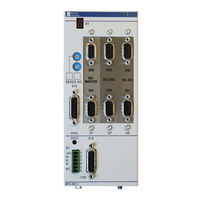
RECO PLC ISP200-R/G2
Rexroth Indramat RECO PLC ISP200-R/G2 Manuals
Manuals and User Guides for Rexroth Indramat RECO PLC ISP200-R/G2. We have
1
Rexroth Indramat RECO PLC ISP200-R/G2 manual available for free PDF download: Project Planning Manual
Rexroth Indramat RECO PLC ISP200-R/G2 Project Planning Manual (86 pages)
Brand:
Rexroth Indramat
| Category:
Industrial Electrical
| Size: 1 MB
Table of Contents
English
3
Table of Contents
3
1 Reco Plc Isp200-R
7
Front View MTS-R01.2 and MTS-R02.2
7
Brief Description of the ISP200-R
8
2 Important Directions for Use
9
Appropriate Use
9
Introduction
9
Areas of Use and Application
10
Inappropriate Use
10
3 Safety Instructions for Electric Drives and Controls
11
Introduction
11
Explanations
11
Hazards by Improper Use
12
General Information
13
Protection against Contact with Electrical Parts
14
Protection against Electric Shock by Protective Low Voltage (PELV)
15
Protection against Dangerous Movements
15
Protection against Magnetic and Electromagnetic Fields During Operation and Mounting
17
Protection against Contact with Hot Parts
18
Protection During Handling and Mounting
18
Battery Safety
19
Protection against Pressurized Systems
19
4 Technical Data
21
General Features
21
Supply Voltage
21
I/O Bus Supply by the Control
21
Derating of the I/O Bus Supply
21
Emc
22
Interfaces
22
Dimensions
23
MTS-R01.2 and MTS-R02.2
23
Installation Sizes of the RMB02.2-02 Module Carrier
24
5 Communication
27
Parameterization of the PROG Interface
27
Parameterization of the COM Interface
28
BT Bus
28
6 Startup
31
Slot Addressing of the Module Carriers
31
Installation Instructions
32
Installation of Module Carriers
32
Arrangement of Module Carriers
32
Connection of Supply Voltage and Watchdog
35
Recobus in the PLC Memory
36
Recobus Diagnosis
37
Status Information and Error Diagnosis
40
Indication of Operating States
40
Indication of Errors
40
Battery
41
Interface Assignment
41
7 Reco Plc Mts-R01.2
43
Brief Description
43
Application Example
44
Type Code
45
8 Reco Plc Mts-R02.2
47
Brief Description
47
Application Example
48
Type Code
49
9 INTERBUS Master Connection
51
Brief Description
51
Setting of the I/O Address
52
Technical Data
52
Fig. 9-3: Technical Data
52
Interface Assignment
53
Fig. 9-4: Pin Assignment of the INTERBUS Diagnosis Interface X64
53
Fig. 9-5: Pin Assignment of the INTERBUS Interface X60 (Remote Bus)
53
10 PROFIBUS DP Connection
55
Brief Description of Master and Slave Connection
55
Fig. 10-1: PROFIBUS Connections
55
Setting the I/O Addresses
56
Fig. 10-2: Setting of the Module Type
56
Status and Diagnosis Information
57
Technical Data
57
Interface Assignment
58
Fig. 10-3: Pin Assignment of the Diagnosis Interface RS232C (X74, X79)
58
Fig. 10-4: Pin Assignment of the PROFIBUS Interface (X70, X75)
58
11 Devicenet Master Connection
59
Brief Description
59
Setting of the I/O Address
60
Fig. 11-2: Maximum Cable Lengths Dependent on the Used Cable
60
Fig. 11-3: Setting of the I/O Address
60
Status and Diagnostic Displays
61
Technical Data
61
Interface Assignment
62
Fig. 11-4: Pin Assignment of the Devicenet Diagnostic Interface X84
62
Fig. 11-5: Pin Assignment of the Devicenet Interface X80
62
12 Serial Interfaces
63
Brief Description
63
Fig. 12-1: P.C.B. SIO 04-B
63
Address and Interrupt Settings
64
Function Blocks
64
Fig. 12-2: Jumper Settings on the P.C.B. SIO 04-B
64
Fig. 12-3: Function Blocks for Interface Handling
64
Technical Data
65
Interface Assignment
65
Fig. 12-4: Pin Assignment of RS 232C X35, X36
65
Fig. 12-5: Pin Assignment of RS422/485 X40, X41
65
13 Networking
67
Networking Via the PROG and COM Interfaces
67
Fig. 13-1: RS485 Connection with INS0619 Connector
67
Fig. 13-2: RS422 Connection with INS0645 Connector
67
ISP200-R in Connection with the BTV20/30
68
Fig. 13-3: ISP200-R Networking with BTV20/30
68
14 Connection of Operator Terminals
69
Applications with the BTV04/05/06
69
Fig. 14-1: MTS-R with Compact Operator Terminals Via an RS422 Interface
69
Fig. 14-2: MTS-R with Compact Operator Terminals Via an RS485 Interface
70
Applications with the BTC06
71
Fig. 14-3: MTS-R with BTC06 Via an RS232 Interface
71
Fig. 14-4: MTS-R with Via an RS422 Interface
72
15 Accessories
73
Selection List of Connectors and Ready-Made Cables
73
Fig. 15-1: MTS-R Accessories
75
Labeling of I/O Modules
76
Fig. 15-2: Labeling Accessories
76
Deutsch
77
Fig. 1-1: MTS-R01.2 and MTS-R02.2
7
Fig. 3-1: Hazard Classification (According to ANSI Z535)
11
Fig. 4-2: RMB02.2-02 Module Carrier
24
Fig. 4-3: Connection of One RMB02.2-02 and Several RMB02.2-04
24
Installation Sizes of the RMB02.2-04 Module Carrier
25
Fig. 5-1: DIP Switch for Parameterization of the PROG Interface
27
Fig. 5-2: Setting of the PROG Interface for the MTS-R01.2 and the MTS-R02.2
27
Fig. 5-3: BT Bus Overview
28
Addressing
29
Fig. 5-4: Storage Requirements of Operating Devices
29
Fig. 5-5: Storage Assignment of BT Bus
29
Fig. 6-1: Setting of Slot Addressing
31
Fig. 6-2: Maximum Number of RMB02.2-04 Carriers Fitted
32
Installation of Modules
33
Fig. 6-3: Maximum Number of RMB02.2-02 and RMB02.2-04 Carriers Fitted
33
Fig. 6-4: Fitting Variants for RMB02.2-02
33
Grounding
34
Fig. 6-5: System Grounding in Connection with the ISP200-R
34
Fig. 6-6: Connection of the Supply Connector X1
35
Fig. 6-7: Recobus I/O Modules in the Memory of the PLC
36
Fig. 6-8: Division of Diagnosis Double Word / Status Information
37
Fig. 6-9: Explanation of Status Bit 31
37
Error Detection by the User
38
Fig. 6-10: Error Detection
38
Fig. 6-11: Explanation of the Diagnosis Bit
38
External Voltage Monitoring
39
Example of an External Power Failure
39
Fig. 6-12: Voltage Monitoring
39
Fig. 6-13: Bit Explanation
39
Fig. 6-14: Example of an External Power Failure
39
Fig. 6-15: Operating States of the ISP200-R
40
Fig. 6-16: Error Codes of the ISP200-R
40
Fig. 6-17: Pin Assignment of the PROG Interface X10 and the COM Interface X16
41
Fig. 6-18: Pin Assignment of the BT Bus X15
41
Fig. 7-1: MTS-R01.2
43
Fig. 7-2: MTS-R01.2 with INTERBUS Connection
44
Fig. 7-3: MTS-R01.2 Type Code
45
Fig. 8-1: MTS-R02.2
47
Fig. 8-2: MTS-R02.2 with INTERBUS Connection and 4 Serial Interfaces
48
Fig. 8-3: MTS-R02.2 Type Code
49
Fig. 9-1: P.C.B. LK IBM 2
51
Fig. 9-2: Setting of DIP Switch S1
52
16 List of Figures
77
17 Service & Support
79
Helpdesk
79
Service-Hotline
79
Internet
79
Vor der Kontaktaufnahme
79
Kundenbetreuungsstellen - Sales & Service Facilities
80
Advertisement
Advertisement
Related Products
Rexroth Indramat Categories
Controller
Control Unit
Amplifier
Industrial Electrical
More Rexroth Indramat Manuals
Login
Sign In
OR
Sign in with Facebook
Sign in with Google
Upload manual
Upload from disk
Upload from URL