
Related Manuals for Pepperl+Fuchs VisuNet GXP RM-GXP1100-22F


Summary of Contents for Pepperl+Fuchs VisuNet GXP RM-GXP1100-22F
- Page 1 SYSTEM MANUAL VisuNet GXP RM-GXP1100-22F RM-GXP1200-22F PC-GXP1100-22F PC-GXP1200-22F...
- Page 2 Association of the Electrical Industry (Zentralverband Elektrotechnik und Elektroindustrie (ZVEI) e.V.) in its most recent version as well as the supplementary clause: "Expanded reservation of proprietorship" Worldwide Pepperl+Fuchs Group Lilienthalstr. 200 68307 Mannheim Germany Telephone: +49 621 776 - 0...
-
Page 3: Table Of Contents
VisuNet GXP Contents Introduction .................... 4 Content of this Document ................4 Target Group, Personnel ................4 Symbols Used ....................5 Product Description................6 Overview......................6 Technical Specifications ................8 Dimensions....................12 Mechanical Installation................ 14 Unpacking ....................14 Electrical Installation................... 16 System Installation .................. -
Page 4: Introduction
VisuNet GXP Introduction Introduction Content of this Document This document contains information that you need in order to use your product throughout the applicable stages of the product life cycle. These can include the following: • Product identification • Delivery, transport, and storage •... -
Page 5: Symbols Used
VisuNet GXP Introduction Symbols Used This document contains symbols for the identification of warning messages and of informative messages. Warning Messages You will find warning messages, whenever dangers may arise from your actions. It is mandatory that you observe these warning messages for your personal safety and in order to avoid property damage. -
Page 6: Product Description
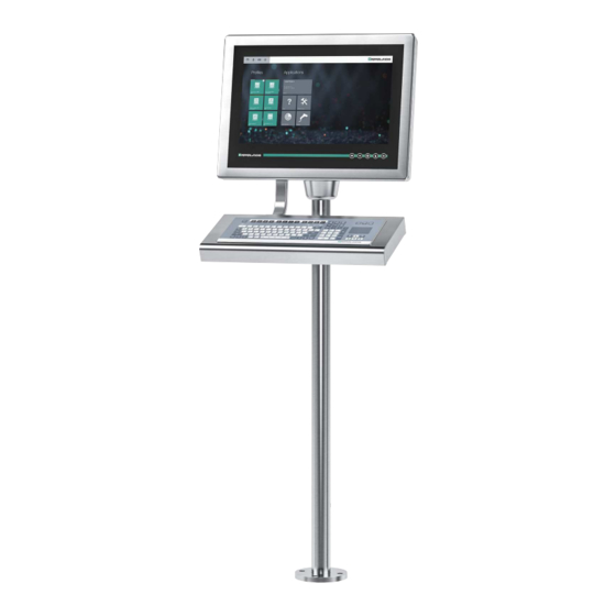
• Computing units: • TCU1100-* and TCU1200-* thin client units that run the latest Pepperl+Fuchs RM Shell firmware. Using standard Ethernet technology, they allow connection to host systems in the non-Ex area. - Page 7 VisuNet GXP Product Description The VisuNet GXP system can also be ordered pre-mounted in an AG-XX00 housing, ready for pedestal or wall mounting. VisuNet GXP Pedestal Mounted with Keyboard/Mouse Figure 2.2 VisuNet GXP workstation mounted in an AG-XX00 housing on a PEDESTAL-XX00-* pedestal with optional EXTA2-* keyboard/mouse (ordered separately) Note For a description of the product model nomenclature, see the VisuNet GXP PC or VisuNet GXP...
-
Page 8: Technical Specifications
VisuNet GXP Technical Specifications Technical Specifications Technical Data RM-GXP* Hardware Processor Intel® Atom™ Bay Trail E3827 1.75 GHz 2048 MB DDR3L Mass storage 32 GByte industrial grade MLC SSD Software Operating system VisuNet RM Shell 5.x (based on Microsoft® Windows® 10 IoT LTSB) Technical Data PC-GXP* Hardware Processor... - Page 9 1 x Ethernet 100/1000BASE-TX (Ex e) or fiber optic 1000Base-SX 1 x USB 2.0 (Ex e) 2 x USB 1.1 (Ex i; intended for Pepperl+Fuchs keyboard and mouse) optional: 1 x barcode reader interface Pepperl+Fuchs Pscan-D/B (Ex i) optional: 1 x barcode reader interface Pepperl+Fuchs IDM160-D-* and...
- Page 10 VisuNet GXP Technical Specifications Mechanical specifications Degree of protection IP66 (individual components and entire system with housing) Material Internal: Panel: anodized aluminum (TCU, PCU, PSU), powder coated aluminum (DPU) External: Bezel: stainless steel AISI 304 (1.4301) System housing: stainless steel AISI 304 (1.4301), beat blasted, typical surface roughness Ra = 0.8 µm Installation Flush-mount installation (requires customized mounting kit)
- Page 11 VisuNet GXP Technical Specifications Note For more technical information, refer to the documentation for the individual components: • Display Units DPU1100-J1* DPU1200-J2* • AC Power Supply Units PSU1100-J1-AC-N0 PSU1200-J2-AC-N0 • DC Power Supply Units PSU1100-J1-DC-N0 PSU1200-J2-DC-N0 • Thin Client Units TCU1100-J1-* TCU1200-J2-* •...
-
Page 12: Dimensions
VisuNet GXP VisuNet GXP Dimensions Product Description Dimensions Note For more options and information, refer to the VisuNet GXP Mounting Options datasheet. Pedestal Mount ~ 400 ~ 400 ø 165 VisuNet GXP system H1 housing installed into AG-XX00 housing with additional PEDESATAL- XX00-* pedestals and EXTA2-* keyboard inside an -F housing with -G mounting version (1-Arm for mounting to AG-XX00 housing) Shown with PEDESTAL-XX00-124-3-304-TRN-N0... - Page 13 VisuNet GXP VisuNet GXP Product Description Dimensions Wall Mount VisuNet GXP system H1 housing installed into AG-XX00 housing with additional WALL-BRACKET-XX00-3-304-N0 and EXTA2 keyboard inside an -F housing with -G mounting version (1-Arm for mounting to AG-XX00 housing) Wall Mount Hole Pattern 11.8...
-
Page 14: Mechanical Installation
VisuNet GXP VisuNet GXP Mechanical Installation Mechanical Installation Panel Mount 17.3 23.5 VisuNet GXP system S1 housing including bezel, prepared for panel mounting, with KIT-PM-XX00-22F-304-N0 kit for panel mounting Mechanical Installation Unpacking Warning! Risk of injury Handling the VisuNet GXP components without gloves may cut fingers, hands, or wrists. Wear gloves at all times during installation. - Page 15 NEVER use a DPU with a scratched screen in a hazardous area. If the surface is damaged in any way, return the DPU to Pepperl+Fuchs at once and replace it with a new one. See chapter 3.3.12 for information about removing the DPU.
-
Page 16: Electrical Installation
VisuNet GXP VisuNet GXP Electrical Installation Mechanical Installation Electrical Installation Warning! Danger of Explosion Cable insulation may become damaged if cables and connection lines are not used in adequate temperature ranges. Thus, short circuits within the cable may occur which in turn may give rise to sparks and/or surface temperatures capable of triggering an ignition. -
Page 17: System Installation
VisuNet GXP VisuNet GXP System Installation Mechanical Installation System Installation 3.3.1 General Installation Information Observe the following requirements when installing the system components. • The equipment must be installed by competent personnel in accordance with the instructions. National laws and regulations must be observed. •... -
Page 18: Preparing For Pedestal Installation
VisuNet GXP VisuNet GXP System Installation Mechanical Installation 3.3.2 Preparing for Pedestal Installation For floor mounting, the preferred installation option uses PEDESTAL-XX00-* with either 3 or 4 cable glands. The pedestal is shipped with a pre-installed rotating coupling with four bolts and a PE wire, which is attached to the pedestal tube. - Page 19 VisuNet GXP VisuNet GXP System Installation Mechanical Installation Figure 3.6 Pedestal adapter hole pattern Preparing the Pedestal for Connection to the Housing 1. Align the pedestal so that the cable glands point away from you. 2. The pedestal must be firmly screwed to the floor. 3.
- Page 20 VisuNet GXP VisuNet GXP System Installation Mechanical Installation Adjusting the Rotation of the Coupling 1. Loosen the worm screws in the inner ring with a hexagon socket wrench.
- Page 21 VisuNet GXP VisuNet GXP System Installation Mechanical Installation 2. Use an appropriate tool to open the locking ring. 3. Adjust the ease of rotation for your application. 4. Tighten the worm screws in the inner ring with a hexagon socket wrench.
-
Page 22: Mounting The Housing Onto The Pedestal
VisuNet GXP VisuNet GXP System Installation Mechanical Installation 3.3.3 Mounting the Housing onto the Pedestal Warning! Risk of injury Lifting the device on your own may lead to injury. Do not attempt to lift the device on your own. Use a crane or get another person to help you. Warning! Risk of injury While the device is resting on the pedestal and the nuts have not yet been fixed to the screws,... - Page 23 VisuNet GXP VisuNet GXP System Installation Mechanical Installation Attaching Housing to Pedestal 1. Align the pedestal bolts to the hole pattern on the bottom of the housing by rotating the ped- estal coupling 90° in relation to the cable glands at the bottom of the pedestal. 2.
- Page 24 VisuNet GXP VisuNet GXP System Installation Mechanical Installation Warning! Damage to the PE wire The PE wire may become damaged if it gets stuck between the pedestal and the housing. Bend the PE wire in such a way that it does not get stuck between the pedestal and the housing.
- Page 25 VisuNet GXP VisuNet GXP System Installation Mechanical Installation 9. While continuing to manually secure the housing (e.g. by holding on to it), tip the display panel toward you until the display comes to rest at its fully opened position, hanging down at an angle from taut cables.
- Page 26 VisuNet GXP VisuNet GXP System Installation Mechanical Installation 3.3.4 Installing Cables in the Pedestal Warning! Pinched cables Ensure that cables do not get pinched or damaged during installation. Note Refer to the manuals of the individual components for information on electrical installation and wiring.
-
Page 27: Installing Cables In The Pedestal
VisuNet GXP VisuNet GXP System Installation Mechanical Installation Pedestal with Three Cable Glands Opening/Wrench Size, Cable Diameter, and Torque Opening Size Wrench Size Cable Diameter Torque 24 mm 7 ... 12 mm 10 Nm 20 mm 3 ...7 mm 5 Nm 20 mm 6 ... - Page 28 VisuNet GXP VisuNet GXP System Installation Mechanical Installation 2. Put the gland nut and ferrule of the cable gland on the cable and slide them a few meters down the length of the cable away from the pedestal. Keep the nut and ferrule on the cable. They will be tightened in a later installation step.
-
Page 29: Grounding The Housing To The Pedestal
VisuNet GXP VisuNet GXP System Installation Mechanical Installation 3.3.5 Grounding the Housing to the Pedestal When installing the VisuNet GXP system, always ensure that all components are properly grounded, including housing and mounting parts (e.g., pedestal and wall bracket) with a cable diameter of at least 4 mm in accordance with IEC 60079-14. - Page 30 VisuNet GXP VisuNet GXP System Installation Mechanical Installation Warning! Risk of electric shock or property damage from inadequate grounding. If you do not ground the device correctly, this could result in potential equalization currents. These currents could hurt operating personnel or cause property damage. Ground the device via the grounding bolt.
- Page 31 VisuNet GXP VisuNet GXP System Installation Mechanical Installation Grounding Concept Housing PE stud (hexagon socket) Contact washer Cable lug Flat washer Spring washer Note For more information on installing the input power and output power cables, refer to the VisuNet GXP PSU manuals.
-
Page 32: Wall Mount Installation
VisuNet GXP VisuNet GXP System Installation Mechanical Installation 3.3.6 Wall Mount Installation Warning! Proper installation on the wall It is the installer's responsibility to select a suitable location with sufficient strength to hold the equipment. It is the installer's responsibility to select the proper screws based on the installation conditions. - Page 33 VisuNet GXP VisuNet GXP System Installation Mechanical Installation Wall Mounting 1. See the VisuNet GXP Mounting Options datasheet for the hole pattern. 2. Install the bracket to the wall. 3. Connect the PE wire from the field to the PE stud on the wall bracket (See figure 3.10 below).
-
Page 34: Mounting The Keyboard
VisuNet GXP VisuNet GXP System Installation Mechanical Installation 3.3.7 Mounting the Keyboard The EXTA2-* is the system keyboard/mouse available with a mounting option (option -G) for the VisuNet GXP AG-XX00 housing. Required Components • VisuNet GXP pre-assembled in AG-XX00 housing •... -
Page 35: Mounting The Idm-* Barcode Reader Holder Bracket
VisuNet GXP VisuNet GXP System Installation Mechanical Installation Note Secure the screws with a medium-strength bolt adhesive, such as Loctite® Threadlocker Blue 243®. Refer to the TCU/PCU and EXTA2 manual for more information on installation and connection. 3.3.8 Mounting the IDM-* Barcode Reader Holder Bracket HOLDER-BRACKET-XX00-IDMx61-B-N (#548267) is a bracket for the IDM-* handheld barcode reader family. - Page 36 VisuNet GXP VisuNet GXP System Installation Mechanical Installation Mounting HOLDER-BRACKET-XX00-IDMx61-B-N to AG-XX00 Housing 1. Open the housing. See chapter 3.3.3 2. Remove the cover plate on the outside right side of the AG-XX00 housing by opening the wing screw that is located on the inside of the housing. 3.
- Page 37 VisuNet GXP VisuNet GXP System Installation Mechanical Installation 5. Press the holder bracket against the housing from the outside and fasten the screw using a torque of 6 Nm. 6. From the inside of the AG-XX00 housing, use the hex key to put the second screw (with lock washer and sealing washer) through the other drilled hole on the bracket.
-
Page 38: Cable Installation For Idm* Readers And Base Stations
VisuNet GXP VisuNet GXP System Installation Mechanical Installation 3.3.9 Cable Installation for IDM* Readers and Base Stations CBL-IDMx60-D-* cables come in lengths of 1.8 m or 3.8 m. They are used to install IDMx60-D- * barcode readers to the VisuNet GXP RM/PC. The cables are compatible with the VisuNet GXP AG-XX00 housing. - Page 39 VisuNet GXP VisuNet GXP System Installation Mechanical Installation 3. Guide the open wire end of the cable through the hole. 4. Place the M16 counter nut over the end of the cable. 5. Pull the socket into the housing and tighten it with the M16 counter nut. Tighten the nut with a torque of 5 Nm.
- Page 40 VisuNet GXP VisuNet GXP System Installation Mechanical Installation Wiring Guide IDM160* and Base Station IDMx61-B-N0* Ex i Cable Terminal Signal Name Direction Assignment Color coding Pin M12 connector Xx.1 Supply green Xx.2 Supply brown Xx.3 Xx.4 Xx.5 Xx.6 white Xx.7 Xx.8 IDM260* Cable...
-
Page 41: Cable Installation For Pscan-D-* Handheld Readers
VisuNet GXP VisuNet GXP System Installation Mechanical Installation 3.3.10 Cable Installation for PSCAN-D-* Handheld Readers The DATL-PSCAN-D-XX00-N0 cable is used to install PSCAN-D-* handheld barcode readers to the VisuNet GXP RM/PC. The cable is compatible with the VisuNet GXP AG-XX00 housing. Required Components •... - Page 42 VisuNet GXP VisuNet GXP System Installation Mechanical Installation 3. Guide the open wire end of the cable through the hole. 4. Place the M16 counter nut over the end of the cable. 5. Pull the socket into the housing and tighten it with the M16 counter nut. Tighten the nut with a torque of 5 Nm.
- Page 43 VisuNet GXP VisuNet GXP System Installation Mechanical Installation Wiring Guide PSCAN-D* Handheld Reader Ex i Cable Pin M12 Terminal Signal Assignment Color coding connector Name Direction Xx.1 Supply yellow Xx.2 Supply brown/gray Xx.3 Xx.4 green Xx.5 Xx.6 white Xx.7 Xx.8 Note For detailed information on electrical installation, refer to the TCU/PCU and PSCAN-D-* barcode reader manuals.
-
Page 44: Closing The Housing
VisuNet GXP VisuNet GXP System Installation Mechanical Installation 3.3.11 Closing the Housing Warning! Risk of injury Fingers can be inured when the display is moved backed into the housing. Wear protective gloves and hold the display panel by the frame when moving it. Warning! Risk of cable damage The cables may become damaged during the closing process. - Page 45 VisuNet GXP VisuNet GXP System Installation Mechanical Installation Figure 3.15 Display panel bolts lined up with the cutout holes on the inner frame 4. Press the DPU and housing together at the top end of the system. From the back of the housing, place one screw in the hole at the upper-left corner and one screw in the hole at the upper-right corner of the housing.
-
Page 46: Dismounting The Display Unit
VisuNet GXP VisuNet GXP System Installation Mechanical Installation 3.3.12 Dismounting the Display Unit If repairs are required, the DPU can be dismounted from the TCU/PCU and replaced. Warning! Danger of Explosion An ignition may be triggered if the TCU/PCU is still energized when its terminal compartment is opened. - Page 47 VisuNet GXP VisuNet GXP System Installation Mechanical Installation 2. To simplify replacement of the DPU, temporarily hold the TCU/PCU in place using cable ties. Put cable ties through both mounting holes at the top-left and top-right corners, and hang the TCU/PCU from the top of the housing frame. Cable ties 3.
-
Page 48: Panel Mount Installation
VisuNet GXP VisuNet GXP System Installation Mechanical Installation 5. Remove the two brackets (1) and the 10 bolts at the top, sides, and bottom of the DPU (2). Remove the carabiners (3) from their brackets, take out the 6 bracket screws (4), and remove the carabiner brackets. - Page 49 VisuNet GXP VisuNet GXP System Installation Mechanical Installation Required Components • VisuNet GXP prepared for panel mounting (S1 option) • Kit for wall mounting (WALL-BRACKET-XX00-3-304-N0), which includes 2 x L-shaped panel mount brackets (1 left, 1 right), 1 x rectangular stiffener frame, 14 x M5 x 25 socket head cap screws (torque 1.8 Nm), and 14 x M5 lock nuts (torque 4 Nm) Required Installation Tools •...
- Page 50 VisuNet GXP VisuNet GXP System Installation Mechanical Installation 2. From the front, place the panel in the cabinet cutout hole (1) and move it to an upright vertical position (2). 3. From inside the cabinet, add the stiffener frame, position it (1) ... (3), and press it against the back of the cabinet wall.
- Page 51 VisuNet GXP VisuNet GXP System Installation Mechanical Installation 4. Prepare the other L-shaped bracket with the mounting screws. 5. Mount the prepared L-shaped bracket to the display unit housing (1), then affix both L- shaped brackets with all screws to the stiffener frame (2). 6.
- Page 52 The cutout dimensions and stud location must match those on the GXP exactly. Figure 3.16 VisuNet GXP flush mounted Note For more options and accessories, contact your local Pepperl+Fuchs sales representative.
-
Page 53: Appendix
D-* barcode readers to the VisuNet GXP Length: 3.8 m SCANNER-HOLDER-U1- 548267 Scanner holder compatible XX00-N0 with AG-XX00 housing 548396 Bracket to mount IDMx61-B- HOLDER-BRACKET-XX00- J1-BT-N0 base station to IDMx61-B-N AG-XX00 housing Note For more options and accessories, contact your local Pepperl+Fuchs sales representative. - Page 54 Pepperl+Fuchs Quality Download our latest policy here: www.pepperl-fuchs.com/quality www.pepperl-fuchs.com © Pepperl+Fuchs · Subject to modifications Printed in Germany 2019-10 /TDOCT-5482AENG...
Need help?
Do you have a question about the VisuNet GXP RM-GXP1100-22F and is the answer not in the manual?
Questions and answers