Table of Contents
Advertisement
Quick Links
Advertisement
Table of Contents

Related Manuals for Pepperl+Fuchs VisuNet IXD RM-IXD2100-19U


Summary of Contents for Pepperl+Fuchs VisuNet IXD RM-IXD2100-19U
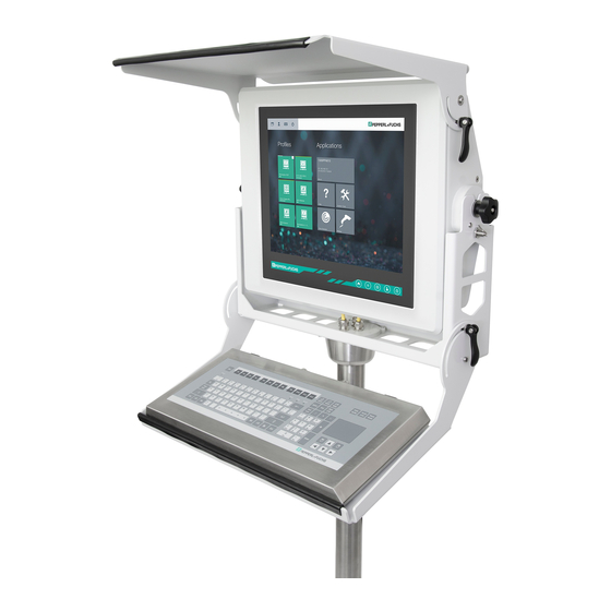
- Page 1 VisuNet IXD RM-IXD2100-19U* PC-IXD2100-19U* Manual...
- Page 2 Phone: +49 621 776 - 0 E-mail: info@de.pepperl-fuchs.com North American Headquarters Pepperl+Fuchs Inc. 1600 Enterprise Parkway Twinsburg, Ohio 44087 Phone: +1 330 425-3555 E-mail: sales@us.pepperl-fuchs.com Asia Headquarters Pepperl+Fuchs Pte. Ltd. P+F Building 18 Ayer Rajah Crescent Singapore 139942 Phone: +65 6779-9091 E-mail: sales@sg.pepperl-fuchs.com https://www.pepperl-fuchs.com...
-
Page 3: Table Of Contents
VisuNet IXD Contents Introduction........................ 4 Content of this Document ................4 Target Group, Personnel ................4 Symbols Used ....................4 Product Description ....................6 Overview ......................6 Technical Specifications ................7 Dimensions....................10 Scope of Delivery..................12 Disposal ......................12 Mechanical Installation ................... -
Page 4: Introduction
VisuNet IXD Introduction Introduction Content of this Document This document contains information that you need in order to use your product throughout the applicable stages of the product life cycle. These can include the following: • Product identification • Delivery, transport, and storage •... - Page 5 VisuNet IXD Introduction Warning Messages You will find warning messages, whenever dangers may arise from your actions. It is mandatory that you observe these warning messages for your personal safety and in order to avoid prop- erty damage. Depending on the risk level, the warning messages are displayed in descending order as fol- lows: Danger! This symbol indicates an imminent danger.
-
Page 6: Product Description
The display and touch sensors are optically bonded with the hardened front glass. • The thin client unit TCU1100-* is a computing unit that runs the latest Pepperl+Fuchs RM Shell 5x or RM Shell 4x firmware. TCUs allow connectivity to various host systems in the safe area using standard Ethernet technology. -
Page 7: Technical Specifications
VisuNet IXD Product Description Several mounting options are available: • Aluminum bezel prepared for yoke mount • Aluminum bezel prepared for wall/VESA mount • Aluminum bezel prepared for panel mount • Installed into EX1 housing AG1 (SS304) front opening, for pedestal/ceiling/wall-arm The above-listed bezel options require additional mounting kits. - Page 8 1 x fiber optic 1000BASE-SX (Multimode) or 1 x fiber optic 1000BASE-LX (Singlemode) 1 x USB 2.0 (Ex e) 2 x USB 1.1 (Ex i; intended for Pepperl+Fuchs keyboard and mouse) 1 x DC or AC power in (via power supply unit)
- Page 9 VisuNet IXD Product Description Mechanical specifications Mass panel with DC: 22 kg , panel with AC: 23 kg , system housing AG1: 19 kg Dimensions panel with DC: 542 mm x 460 x 132 mm panel with AC: 542 mm x 460 mm x 149 mm panel with housing: 582 mm x 490 mm x 224 Note For more technical information such as electrical data and connection details, refer to the...
-
Page 10: Dimensions
VisuNet IXD Product Description Label for DC Version in AG1 Housing Label for AC Version in AG1 Housing Dimensions Panel Dimensions with Bezel 149.2 Figure 2.1 Panel cut-out dimensinons with bezel... - Page 11 VisuNet IXD Product Description Yoke-Mount Dimensions Figure 2.2 Yoke-mount dimensions with optional sunshield and keyboard tray Dimensions with AG1 Housing and Pedestal Figure 2.3 Dimensions with AG1 housing and pedestal...
-
Page 12: Scope Of Delivery
VisuNet IXD Product Description Scope of Delivery The items included with delivery vary depending on the options selected. See the mechanical installation chapters in this manual as well as the IXD and component datasheets on www.pep- perl-fuchs.com for information about available options. Disposal Follow all local and any other requirements for disposing of electronic equipment. -
Page 13: Mechanical Installation
VisuNet IXD Mechanical Installation Mechanical Installation Conditions of Safe Use • The display does not pose an electrostatic discharge hazard under normal use condi- tions. Use only water damp cloth and allow to air dry for cleaning device. Do not use or install in high charge areas. -
Page 14: Installation Environment
Avoid direct sunlight on the IXD display, components, and housing. • If the available shade is insufficient, the optional sunshield can provide protection. If the sunshield is insufficient, contact Pepperl+Fuchs to find an engineered solution that pro- vides enough mechanical protection against sunlight. -
Page 15: Preparing The Ixd
NEVER use a display unit with a scratched front screen in a hazardous area. If the surface is damaged in any way, return the display unit to Pepperl+Fuchs at once and replace it with a new one. Yoke Mount Installation with Pedestal 3.5.1... -
Page 16: Preparing The Pedestal
VisuNet IXD Mechanical Installation 3.5.2 Preparing the Pedestal For floor mounting with a yoke bracket, the preferred pedestal option is PEDESTAL-XX00-124- 3-304-TRN-N0. The pedestal is shipped with a pre-installed rotating coupling and a ground cable, which is attached to the pedestal tube. Note The pedestal comes with bolts attached to the coupling. -
Page 17: Attaching The Ixd To The Yoke And Pedestal
VisuNet IXD Mechanical Installation Attach the cable to the pull wire with a small cable tie and adhesive tape. Pull the cable through the cable entry and out the top of the pedestal. Repeat the preceding steps for each cable to be routed through the pedestal. Place the O-ring into the channel of the coupling. - Page 18 VisuNet IXD Mechanical Installation Required Components • Prepared pedestal. See chapter 3.5.2 for instructions on preparing the pedestal. • IXD with yoke knobs and washers pre-assembled • Yoke frame with loose hardware (including 2 x button head locking screws and 1 x spring plunger) •...
- Page 19 VisuNet IXD Mechanical Installation Attaching Yoke Frame to Pedestal 2 x socket head screws inserted loosely into pedestal prior to installing yoke frame Yoke frame orientation is correct when large threaded hole is on the right side. 2 x additional socket head screws to secure the yoke frame to the pedestal Installation Steps Insert 2 x socket head screws (1) into the pedestal coupling.
- Page 20 VisuNet IXD Mechanical Installation Tighten all 4 screws to 7.5 Nm. Apply a small amount of Loctite 243 to each screw prior to installation. Inserting IXD into Yoke Frame Knobs on IXD 2 x button head socket screws Spring plunger Warning! Risk of personal injury and equipment damage Secure IXD during installation.
- Page 21 VisuNet IXD Mechanical Installation Install the spring plunger into the large threaded hole on the right side of the yoke frame (3). Thread the plunger until it stops, then back it off approximately one half turn. Tighten the hex jam nut to 15 Nm. Apply a small amount of Loctite 243 to the threads on the end of the plunger prior to installation.
- Page 22 VisuNet IXD Mechanical Installation Connect the ground wire from the pedestal to the bottom of the gland plate (2). Tighten the ground hardware to 4 Nm. Figure 3.3 Ground hardware configuration Housing ground bolt (hexagon socket) Contact washer Cable lug Flat washer Spring washer Lower the gland plate assembly into place.
- Page 23 VisuNet IXD Mechanical Installation Ground Connection from PSU to DPU The ground connection from the PSU to the DPU is assembled in the factory. If you replace the DPU or PSU, reestablish the ground connection in the same configuration. Tighten the ground hardware to 4 Nm.
-
Page 24: Installing The Keyboard Tray Kit
VisuNet IXD Mechanical Installation 3.5.4 Installing the Keyboard Tray Kit Required Components • Keyboard tray kit with loose hardware to be assembled to the yoke frame by the customer. Required Installation Tools • 3 mm hex key for attaching screws to the yoke bracket •... - Page 25 VisuNet IXD Mechanical Installation Installation Steps Preassemble the cam levers (1). Place the two components on each threaded cam shaft as shown below, with the curved side of the rubber washer fitted against the cam lever. Ensure that the headless screw is positioned approximately even with the head of each cam lever. Bring the keyboard tray into position such that the center holes (2) are aligned with the lower threaded holes on the sides of the yoke frame.
-
Page 26: Installing The Sunshield Kit
VisuNet IXD Mechanical Installation 3.5.5 Installing the Sunshield Kit Required Components • Sunshield kit with loose hardware to be assembled to the yoke frame by the customer. Required Installation Tools • 4 mm hex key for attaching screws to the yoke frame •... - Page 27 VisuNet IXD Mechanical Installation Installation Steps Preassemble the cam levers (1). Place the two included components on each threaded cam shaft as shown below, with the curved side of the rubber washer fitted against the cam lever. Ensure that the headless screw is positioned approximately even with the head of each cam lever.
-
Page 28: Panel Mount Installation
VisuNet IXD Mechanical Installation Panel Mount Installation Required Components • Panel mount kit with loose hardware to be assembled to the IXD by the customer Required Installation Tools • 4 mm hex key for clamping screws • 5 mm hex key for attaching panel mount brackets to the IXD •... -
Page 29: Wall Mount Assembly
VisuNet IXD Mechanical Installation Installation Steps Start to thread 18 x socket head screws into the threaded holes on the panel mount brackets. Attach the lower panel mount bracket (1) to the IXD using 5 x washers and 5 x socket head screws. - Page 30 VisuNet IXD Mechanical Installation Wall Mounting the IXD Figure 3.5 Wall mount configuration Installation Steps Lay the IXD display-side down on a flat surface. Remove the 4 x flat-head socket screws from the VESA bracket. Slide the VESA bracket over and lift it up. Position the wall mount bracket with the slots facing upward.
-
Page 31: Ag1 Assembly
VisuNet IXD Mechanical Installation AG1 Assembly 3.8.1 Preparation for Floor Mounting with AG1 Housing Warning! Proper installation on the floor It is the installer's responsibility to select a suitable location with sufficient strength to hold the equipment. It is the installer's responsibility to select the proper screws based on the installa- tion conditions. -
Page 32: Preparing The Standardline Pedestal
VisuNet IXD Mechanical Installation StandardLine Pedestal Floor-Mount Hole Pattern 3.8.2 Preparing the StandardLine Pedestal Pedestals are shipped with an attached ground wire and screws for mounting the IXD housing to the pedestal: 6 x M8 countersunk screws and 2 x M6 countersunk screws. - Page 33 VisuNet IXD Mechanical Installation StandardLine Pedestal Pre-installed ground wire Top cable opening Cable glands...
- Page 34 VisuNet IXD Mechanical Installation Bottom of Pedestal ground bolt M25 opening M20 opening M20 plug Warning! Connection to the ground bolt Connection to the ground bolt is mandatory. Opening Size Wrench Size Cable Diameter Torque 24 mm 7 ... 13 mm 12 Nm 29 mm 9 ...
- Page 35 VisuNet IXD Mechanical Installation Pull the cable through the cable entry and out the top of the pedestal. Pull the cable through the pedestal so that 50 cm of cable is hanging out of the top of the pedestal. Repeat the preceding steps for each cable that must be routed through the pedestal.
-
Page 36: Attaching The Pedestal To The Housing
VisuNet IXD Mechanical Installation 3.8.3 Attaching the Pedestal to the Housing Warning! Risk of injury Lifting the equipment on your own may cause injury. Mounting the AG1 Housing to the Pedestal Rest the pedestal on the box that the AG1 housing was shipped in. Position the pedestal and box behind the housing. - Page 37 VisuNet IXD Mechanical Installation Tighten the 6 x M8 screws in a criss-cross pattern to 20 Nm. Tighten the 2 x M6 screws to 12 Nm.
- Page 38 VisuNet IXD Mechanical Installation Positioning and Floor-Mounting the IXD Remove the box from under the pedestal and carefully position the system upright on the floor with a crane or the help of another person. Mount the pedestal onto the floor using suitable screws. Warning! Proper floor mounting It is the installer's responsibility to select a suitable location with sufficient...
-
Page 39: Ag1 Housing Assembly
VisuNet IXD Mechanical Installation 3.8.4 AG1 Housing Assembly Warning! Risk of personal injury and equipment damage Lifting the IXD housing on your own may cause injury or damage the device. Required Components • IXD prepared for AG1 installation with panel mount or AG1 adapter and gaskets •... -
Page 40: Opening The Ag1 Housing
VisuNet IXD Mechanical Installation Installation Steps Guide the IXD into the AG1 housing. While holding the IXD in the housing, install a few washers and socket head screws by hand to keep the IXD in place. Insert a total of 14 x washers and 14 x screws in a uniform criss-cross pattern. Tighten the 14 x screws to 6 Nm. -
Page 41: Grounding The Ag1 Housing To The Pedestal
VisuNet IXD Mechanical Installation Pull the right side of the housing front away from the back part of the housing. 3.8.6 Grounding the AG1 Housing to the Pedestal Warning! Customer responsibility to verify grounding path Check the grounding path after completing system installation. Warning! Connection to the ground bolts Connection to the ground bolts is mandatory. - Page 42 VisuNet IXD Mechanical Installation Connecting the Ground Wires Remove the nuts and washers from the PE stud on the inside-back of the AG1 housing. Connect the pre-installed ground wires from the the housing and pedestal to the ground bolt. Replace the nuts and washers. Fasten the nuts and washers with a torque of 7.5 Nm.
- Page 43 VisuNet IXD Mechanical Installation Figure 3.8 Grounding Concept Housing Ground bolt (hexagon socket) Contact washer Cable lug Flat washer Spring washer...
- Page 44 VisuNet IXD Mechanical Installation Ground Connection from PSU to DPU The ground connection from the PSU to the DPU is assembled in the factory. If you replace the DPU or PSU, reestablish the ground connection in the same configuration. Tighten the ground hardware to 4 Nm.
-
Page 45: Mounting The Keyboard
VisuNet IXD Mechanical Installation 3.8.7 Mounting the Keyboard Remove the plug and screws from the bottom of the housing To remove the plug, open the housing (see chapter 3.8.5). Hold the inside nut while removing the plug from the outside with a flat-head screwdriver. - Page 46 VisuNet IXD Mechanical Installation Pull the keyboard wire through the plug and tighten the screws to 4.5 Nm. Note The keyboard is an intrinsically safe device. Refer to the control drawings and relevant installation requirements. For proper electrical termination of the keyboard, refer to the TCU/PCU and EXTA2 keyboard manuals.
-
Page 47: Appendix
KIT-IXD-PM-19U Panel mount kit 548266 AG1-19S-304A-NN-NN-N0 AG1 housing 548392 KIT-IXD19-KBT1 Keyboard tray for yoke mount 548393 KIT-IXD19-KBT2 Keyboard tray for wall mount 548394 KIT-IXD19-SUNSHIELD Sunshield for yoke mount Note For more options and accessories, contact your local Pepperl+Fuchs sales representative. - Page 48 Pepperl+Fuchs Quality Download our latest policy here: www.pepperl-fuchs.com/quality www.pepperl-fuchs.com © Pepperl+Fuchs · Subject to modifications Printed in Germany / DOCT-6258B...
Need help?
Do you have a question about the VisuNet IXD RM-IXD2100-19U and is the answer not in the manual?
Questions and answers