Table of Contents
Advertisement
Quick Links
Advertisement
Table of Contents

Related Manuals for Pepperl+Fuchs VisuNet GXP RM-GXP1100-22F


Summary of Contents for Pepperl+Fuchs VisuNet GXP RM-GXP1100-22F
- Page 1 VisuNet GXP RM-GXP1100-22F RM-GXP1200-22F PC-GXP1100-22F PC-GXP1200-22F Manual...
- Page 2 Phone: +49 621 776 - 0 E-mail: info@de.pepperl-fuchs.com North American Headquarters Pepperl+Fuchs Inc. 1600 Enterprise Parkway Twinsburg, Ohio 44087 Phone: +1 330 425-3555 E-mail: sales@us.pepperl-fuchs.com Asia Headquarters Pepperl+Fuchs Pte. Ltd. P+F Building 18 Ayer Rajah Crescent Singapore 139942 Phone: +65 6779-9091 E-mail: sales@sg.pepperl-fuchs.com https://www.pepperl-fuchs.com...
-
Page 3: Table Of Contents
VisuNet GXP Contents Introduction........................ 4 Content of this Document ................4 Target Group, Personnel ................4 Symbols Used ....................5 Product Description ....................6 Overview ......................6 Technical Specifications ................9 Dimensions....................13 Mechanical Installation ................... 16 Unpacking ....................16 Electrical Installation................... -
Page 4: Introduction
VisuNet GXP Introduction Introduction Content of this Document This document contains information that you need in order to use your product throughout the applicable stages of the product life cycle. These can include the following: • Product identification • Delivery, transport, and storage •... -
Page 5: Symbols Used
VisuNet GXP Introduction Symbols Used This document contains symbols for the identification of warning messages and of informative messages. Warning Messages You will find warning messages, whenever dangers may arise from your actions. It is mandatory that you observe these warning messages for your personal safety and in order to avoid prop- erty damage. -
Page 6: Product Description
Product Description Overview Pepperl+Fuchs VisuNet GXP workstations are ATEX/IECEx certified, UL Listed PCs or thin-cli- ent based remote monitors intended for use in potentially explosive atmospheres such as Zones 1/21 and 2/22, Class I/II, Division 2, and Class III. Two display sizes are available—19 inch and 21.5 inch. - Page 7 VisuNet GXP Product Description VisuNet GXP Panel Components Figure 2.1 VisuNet GXP panel components Bezel for housing and panel mounting Computing unit (TCU or PCU): processor, SSD and memory, Ex circuits, interface modules Power supply unit: DC or AC option, backpacked (panel-mount) or stand- alone (in system enclosure) Display unit: display, touch screen, hardened front glass The VisuNet GXP system can also be ordered pre-mounted in an AG-XX00 housing, ready for...
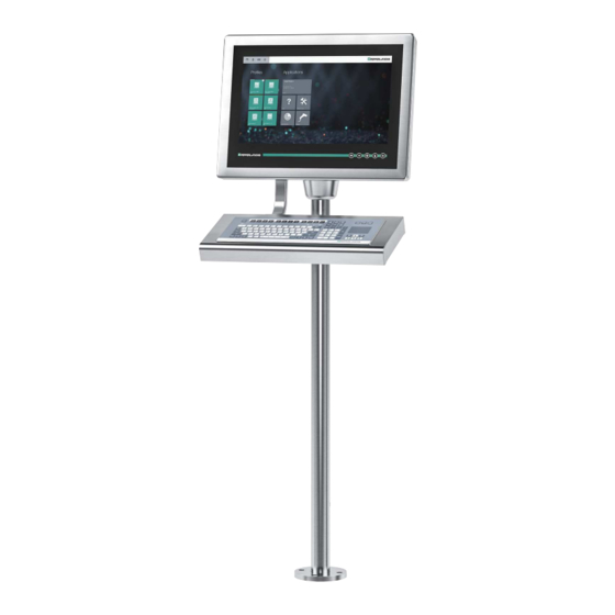
- Page 8 VisuNet GXP Product Description VisuNet GXP Pedestal Mounted with Keyboard/Mouse Figure 2.2 VisuNet GXP workstation mounted in an AG-XX00 housing on a PEDESTAL-XX00-* pedestal with optional EXTA2-* keyboard/mouse (ordered separately) Note For a description of the product model nomenclature, see the VisuNet GXP PC or VisuNet GXP RM product datasheets at www.pepperl-fuchs.com.
-
Page 9: Technical Specifications
VisuNet GXP Product Description Technical Specifications Technical Data RM-GXP* Hardware Processor Intel® Atom™ Apollo Lake E3930 4 GB Mass storage 32 GByte industrial grade MLC SSD Software Operating system VisuNet RM Shell 5.x (based on Microsoft® Windows 10 IoT Enterprise 2019 LTSC (x64)) Technical Data PC-GXP* Hardware Processor... - Page 10 1 x fiber optic 1000BASE-SX (Multimode) or 1 x fiber optic 1000BASE-LX (Singlemode), 1 x USB 2.0 (Ex e), 2 x USB 1.1 (Ex i; intended for Pepperl+Fuchs keyboard and mouse), 1 x DC or AC power in (via power supply unit)
- Page 11 VisuNet GXP Product Description Ambient conditions Shock resistance 18 shocks 15 g , 11 ms all axis, IEC 60068-2- Vibration resistance 10 ... 150 Hz, +/- 0.075 mm , 1g, 10 cycles per axis according to EN60068-2-6 Mechanical specifications Degree of protection IP66 (individual components and entire sys- tem with housing) Material...
- Page 12 VisuNet GXP Product Description Note For more technical information, refer to the documentation for the individual components: • Display Units DPU1100-J1* and DPU1200-J2* • AC Power Supply Units PSU1100-J1-AC-N0 and PSU1200-J2-AC-N0 • DC Power Supply Units PSU1100-J1-DC-N0 and PSU1200-J2-DC-N0 • Thin Client Units TCU1100-J1-* and TCU1200-J2-* •...
-
Page 13: Dimensions
VisuNet GXP Product Description Dimensions Note For more options and information, refer to the VisuNet GXP Mounting Options datasheet. Pedestal Mount ~ 400 ~ 400 ø 165 VisuNet GXP system H1 housing installed into AG-XX00 housing with additional PEDESATAL- XX00-* pedestals and EXTA2-* keyboard inside an -F housing with -G mounting version (1-Arm for mounting to AG-XX00 housing) Shown with PEDESTAL-XX00-124-3-304-TRN-N0 Shown with PEDESTAL-XX00-124-4-304-TRN-N0... - Page 14 VisuNet GXP Product Description Wall Mount Figure 2.3 VisuNet GXP system H1 housing installed into AG-XX00 housing with additional WALL- BRACKET-XX00-3-304-N0 and EXTA2 keyboard inside an -F housing with -G mounting version (1-Arm for mounting to AG-XX00 housing) Wall Mount Hole Pattern Figure 2.4...
- Page 15 VisuNet GXP Product Description Panel Mount 17.3 23.5 Figure 2.5 VisuNet GXP system S1 housing including bezel, prepared for panel mounting, with KIT- PM-XX00-22F-304-N0 kit for panel mounting...
-
Page 16: Mechanical Installation
NEVER use a DPU with a scratched screen in a hazardous area. If the surface is damaged in any way, return the DPU to Pepperl+Fuchs at once and replace it with a new one. See chapter 3.3.13 for information about removing the DPU. - Page 17 VisuNet GXP Mechanical Installation Using Foam Brackets During Installation Figure 3.2 To help protect the VisuNet GXP components once they have been removed from the box, use the enclosed foam brackets. Figure 3.3 To protect the DPU front screen, place the VisuNet GXP face down onto the foam brackets.
-
Page 18: Electrical Installation
VisuNet GXP Mechanical Installation Electrical Installation Warning! Danger of Explosion Cable insulation may become damaged if cables and connection lines are not used in ade- quate temperature ranges. Thus, short circuits within the cable may occur which in turn may give rise to sparks and/or surface temperatures capable of triggering an ignition. -
Page 19: System Installation
VisuNet GXP Mechanical Installation System Installation 3.3.1 General Installation Information Observe the following requirements when installing the system components. • The equipment must be installed by competent personnel in accordance with the instruc- tions. National laws and regulations must be observed. •... -
Page 20: Preparing For Pedestal Installation
VisuNet GXP Mechanical Installation 3.3.2 Preparing for Pedestal Installation For floor mounting, the preferred installation option uses PEDESTAL-XX00-* with either 3 or 4 cable glands. The pedestal is shipped with a pre-installed rotating coupling with four bolts and a PE wire, which is attached to the pedestal tube. Figure 3.4 Pedestal with optional 3 or 4 cable glands PEDESTAL-XX00-124-3-304-TRN-N0 with 3 cable glands... - Page 21 VisuNet GXP Mechanical Installation Figure 3.5 Pedestal with PE wire PE wire Figure 3.6 Pedestal adapter hole pattern...
- Page 22 VisuNet GXP Mechanical Installation Preparing the Pedestal for Connection to the Housing Align the pedestal so that the cable glands point away from you. The pedestal must be firmly screwed to the floor. Bend the PE wire with a max. radius of 20 mm and place it within the pedestal tube. Place the O-ring and sealant into the channel of the coupling.
-
Page 23: Mounting The Housing Onto The Pedestal
VisuNet GXP Mechanical Installation 3.3.3 Mounting the Housing onto the Pedestal Warning! Risk of injury Lifting the device on your own may lead to injury. Do not attempt to lift the device on your own. Use a crane or get another person to help you. Warning! Risk of injury While the device is resting on the pedestal and the nuts have not yet been fixed to the screws,... - Page 24 VisuNet GXP Mechanical Installation Attaching Housing to Pedestal Align the pedestal bolts to the hole pattern on the bottom of the housing by rotating the pedestal coupling 90° in relation to the cable glands at the bottom of the pedestal. Carefully place the housing face down on an even, cushioned surface.
- Page 25 VisuNet GXP Mechanical Installation Opening the AG-XX00 Housing Figure 3.7...
- Page 26 VisuNet GXP Mechanical Installation Figure 3.8 Slowly lower the DPU until the hinges engange. While continuing to manually secure the housing (e.g. by holding on to it), tip the display panel toward you until the display comes to rest at its fully opened position and the hinges are stretched out.
- Page 27 VisuNet GXP Mechanical Installation Figure 3.9...
- Page 28 VisuNet GXP Mechanical Installation Tigthen the M6 U-washers onto the pedestal bolts using a torque of 7.5 Nm. Note Optional: Secure the nuts with a medium-strength bolt adhesive such as Loctite® Threadlocker Blue 243®...
-
Page 29: Installing Cables In The Pedestal
VisuNet GXP Mechanical Installation 3.3.4 Installing Cables in the Pedestal Warning! Pinched cables Ensure that cables do not get pinched or damaged during installation. Note Refer to the manuals of the individual components for information on electrical installation and wiring. Required Installation Tools •... - Page 30 VisuNet GXP Mechanical Installation Pedestal with Three Cable Glands Opening/Wrench Size, Cable Diameter, and Torque Opening Size Wrench Size Cable Diameter Torque 24 mm 7 ... 12 mm 10 Nm 20 mm 3 ...7 mm 5 Nm 20 mm 6 ... 10 mm 5 Nm...
- Page 31 VisuNet GXP Mechanical Installation Installing Cables Based on how many cables and openings are required (i.e., power and Ethernet), remove the appropriate number of cable glands at the bottom of the pedestal. Put the gland nut and ferrule of the cable gland on the cable and slide them a few meters down the length of the cable away from the pedestal.
- Page 32 VisuNet GXP Mechanical Installation Pull the cable through the pedestal so that 50 cm of the cable is hanging out of the top of the pedestal. Repeat the preceding steps for each cable that must be routed through the pedestal. The pedestal is now ready for connection.
-
Page 33: Grounding The Housing To The Pedestal
VisuNet GXP Mechanical Installation 3.3.5 Grounding the Housing to the Pedestal When installing the VisuNet GXP system, always ensure that all components are properly grounded, including housing and mounting parts (e.g., pedestal and wall bracket) with a cable diameter of at least 4 mm in accordance with IEC 60079-14. - Page 34 VisuNet GXP Mechanical Installation Danger! Explosion hazard from wrong or missing grounding Wrong or missing grounding can cause sparks. This can ignite the surrounding potentially explosive atmosphere. • Ground the device. Observe the grounding requirements. • Ensure that external ground connections exist, are in good condition, and are not dam- aged or corroded.
- Page 35 VisuNet GXP Mechanical Installation Grounding Concept Figure 3.12 Note For more information on installing the input power and output power cables, refer to the VisuNet GXP PSU manuals.
-
Page 36: Installation Of The Ferrite Ring
VisuNet GXP Mechanical Installation 3.3.6 Installation of the Ferrite Ring In order to meet certain electrical noise emission limits and to protect the VisuNet GXP from external influences, it is necessary to install a ferrite core on the Power Supply cable connected to the PSU. -
Page 37: Wall Mount Installation
VisuNet GXP Mechanical Installation 3.3.7 Wall Mount Installation Warning! Proper installation on the wall It is the installer's responsibility to select a suitable location with sufficient strength to hold the equipment. It is the installer's responsibility to select the proper screws based on the installa- tion conditions. - Page 38 VisuNet GXP Mechanical Installation Wall Mounting See the VisuNet GXP Mounting Options datasheet for the hole pattern. Install the bracket to the wall. Connect the PE wire from the field to the PE stud on the wall bracket. Mount the VisuNet GXP to the bolts on the wall bracket. Follow the relevant steps required for mounting the housing to a pedestal.
-
Page 39: Mounting The Keyboard
VisuNet GXP Mechanical Installation 3.3.8 Mounting the Keyboard The EXTA2-* is the system keyboard/mouse available with a mounting option for the VisuNet GXP AG-XX00 housing. Required Components • VisuNet GXP pre-assembled in AG-XX00 housing • EXTA2-* keyboard/mouse (screws included) Required Installation Tools •... - Page 40 VisuNet GXP Mechanical Installation Fasten the four screws with a torque of 6 Nm. Note Secure the screws with a medium-strength bolt adhesive, such as Loctite® Threadlocker Blue 243®. Refer to the TCU/PCU manual for more information on installation and connection.
-
Page 41: Mounting The Idm-* Barcode Reader Holder Bracket
VisuNet GXP Mechanical Installation 3.3.9 Mounting the IDM-* Barcode Reader Holder Bracket SCANNER-HOLDER-U1-XX00-N0 is a holder for the IDM-* handheld barcode reader family. The holder is compatible with the VisuNet GXP AG-XX00 housing. Required Components • VisuNet GXP pre-assembled in AG-XX00 housing •... - Page 42 VisuNet GXP Mechanical Installation Mounting SCANNER-HOLDER-U1-XX00-N0 to AG-XX00 Housing Open the housing. See chapter 3.3.3 Figure 3.17 Remove the cover plate on the outside right side of the AG-XX00 housing by opening the wing screw that is located on the inside of the housing.
- Page 43 VisuNet GXP Mechanical Installation Connect the adapter (included with the scanner holder in delivery) to the scanner holder with the enclosed screws. From the inside-right of the AG-XX00 housing, use a hex key to put the first screw (with lock washer and sealing washer) through one of the drilled holes on the adapter.
- Page 44 VisuNet GXP Mechanical Installation Figure 3.18 Dimensions with scanner holder Follow the same steps to mount HOLDER-BRACKET-XX00-IDMx61-B-N (#548396). This bracket holds the IDM base station.
- Page 45 VisuNet GXP Mechanical Installation Figure 3.19 HOLDER-BRACKET-XX00-IDMx61-B-N (screws and adapter included)
- Page 46 VisuNet GXP Mechanical Installation Figure 3.20...
-
Page 47: Cable Installation For Idm-* Readers And Base Stations
VisuNet GXP Mechanical Installation 3.3.10 Cable Installation for IDM-* Readers and Base Stations DATL-IDM-DB-S-XX00-N0 and CBL-IDMx60-D-* are used to install IDM-Z1-160-D-1D-J1-*, IDM-160-D-1D-*, IDM-Z1-260-D-2D-J1-S1-N-N0, or IDM-Z1-x61-B-J1-BT-N0 and IDM-x61-* to the VisuNet GXP RM/PC. The cables are compatible with the VisuNet GXP AG-XX00 hous- ing. - Page 48 VisuNet GXP Mechanical Installation Installing the Cable DATL-IDM-DB-S-XX00-N0 Open the housing. See chapter 3.3.3 Remove the plug at the bottom-right side of the housing by holding the screw steady from below with a screwdriver while loosening the screw from above with a wrench. Guide the open wire end of the cable DATL-IDM-DB-S-XX00-N0 through the hole.
- Page 49 VisuNet GXP Mechanical Installation Pull the socket into the housing and tighten it with the M16 counter nut. Tighten the nut with a torque of 5 Nm. Protect the cable from mechanical damage by fastening it with a cable tie. Route the cable through the cable gland on the TCU/PCU.
-
Page 50: Cable Installation For Pscan-D-* Handheld Readers
VisuNet GXP Mechanical Installation DATL-IDM-DB-S-XX00-N0 to IDM-Z1-260* Cable Terminal Signal Name Direction Assignment Color coding Pin M12 con- nector Xx.1 Supply green Xx.2 white Xx.3 Xx.4 Xx.5 Supply brown Xx.6 Xx.7 Xx.8 Note For detailed information on electrical installation, refer to the TCU/PCU and IDM* barcode reader manuals. - Page 51 VisuNet GXP Mechanical Installation Installing DATL-PSCAN-D-XX00-N0 Open the housing. See chapter 3.3.3 Remove the plug at the bottom-right side of the housing by holding the screw steady from below with a screwdriver while loosening the screw from above with a wrench. Guide the open wire end of the cable through the hole.
- Page 52 VisuNet GXP Mechanical Installation Pull the socket into the housing and tighten it with the M16 counter nut. Tighten the nut with a torque of 5 Nm. Protect the cable from mechanical damage by fastening it with a cable tie. Route the cable through the cable gland on the TCU/PCU.
-
Page 53: Closing The Housing
VisuNet GXP Mechanical Installation Connecting the PSCAN-D-* Barcode Reader Connect the plug of the barcode reader to the socket and tighten it firmly. Coded Plug and Socket Figure 3.22 The plug and socket are coded. Match the coding on the plug and socket before tightening. 3.3.12 Closing the Housing Warning! - Page 54 VisuNet GXP Mechanical Installation Closing the AG-XX00 Housing Slowly lift the DPU into an upright position until the bolts touch the inner frame of the housing. Figure 3.23...
- Page 55 VisuNet GXP Mechanical Installation Figure 3.24 Display panel bolts lined up with the cutout holes of the housing.
- Page 56 VisuNet GXP Mechanical Installation Press the DPU and housing together at the top end of the system. From the back of the housing, place one screw in the hole at the upper-left corner and one screw in the hole at the upper-right corner of the housing.
-
Page 57: Dismounting The Display Unit
VisuNet GXP Mechanical Installation 3.3.13 Dismounting the Display Unit If repairs are required, the DPU can be dismounted from the TCU/PCU and be replaced. Nuts for fixing the hinges are included either with the VisuNet GXP System or with the housing AGxx as replacement part. - Page 58 VisuNet GXP Mechanical Installation Remove the PE wire from the PE stud on the back of the DPU. Figure 3.28 To simplify replacement of the DPU, temporarily hold the TCU/PCU in place using cable ties. Put cable ties through both mounting holes at the top-left and top-right corners, and hang the TCU/PCU from the top of the housing frame.
- Page 59 VisuNet GXP Mechanical Installation Figure 3.29 Figure 3.30...
- Page 60 VisuNet GXP Mechanical Installation Now the DPU can be removed from the housing. During the removal process, hold the DPU steady so it cannot fall down, preferably with the help of another person. Place the DPU on an even, cushioned surface after removal. To remove the DPU from the housing, remove the 4 screws that hold the hinges to the DPU (1).
- Page 61 VisuNet GXP Mechanical Installation Note To mount the new DPU, perform the above steps in reverse. 1. Fix the hinges with the four nuts. 2. Mount the PCU/TCU onto the DPU (please refer for further information to the DPU1100-* and DPU1200-* Manual). 3.
-
Page 62: Panel Mount Installation
VisuNet GXP Mechanical Installation 3.3.14 Panel Mount Installation Warning! Proper installation It is the installer's responsibility to select a suitable location with sufficient strength to hold the equipment. It is the installer's responsibility to select the proper screws based on the installa- tion conditions. - Page 63 VisuNet GXP Mechanical Installation The kit for panel mounting can be ordered separately. For ordering details, see chapter 4.1. Note There are two different mounting brackets—they are not identical items. Figure 3.33 Cut out dimensions for panel mounting the VisuNet GXP 21,5" Panel Mounting the GXP Mount the first L-shaped bracket to the back of the display unit.
- Page 64 VisuNet GXP Mechanical Installation From the front, place the panel in the cabinet cutout hole (1) and move it to an upright vertical position (2). From inside the cabinet, add the stiffener frame, position it (1) ... (3), and press it against the back of the cabinet wall.
- Page 65 VisuNet GXP Mechanical Installation Prepare the other L-shaped bracket with the mounting screws. Mount the prepared L-shaped bracket to the display unit housing (1), then affix both L-shaped brackets with all screws to the stiffener frame (2). Tighten all screws in a criss-cross pattern using 1.8 Nm torque for the 14 x M5 x 25 socket head cap screws and 4 Nm for the 10 x M5 lock nuts.
- Page 66 The cutout dimensions and stud location must match those on the GXP exactly. Figure 3.34 VisuNet GXP flush mounted Note For more options and accessories, contact your local Pepperl+Fuchs sales representative.
-
Page 67: Appendix
VisuNet GXP Appendix Appendix Accessories Mounting and Installation Item Number Type Code Description 548003 PEDESTAL-XX00-124-3-304- Swivel pedestal, floor mount TRN-N0 Compatible with AG-XX00-* housing 3 cable glands 548306 PEDESTAL-XX00-124-4-304- Swivel pedestal, floor mount TRN-N0 Compatible with AG-XX00-* housing 4 cable glands 548071 WALL-BRACKET-XX00-3- Adapter for wall mounting... - Page 68 VisuNet GXP Appendix Note For more options and accessories, contact your local Pepperl+Fuchs sales representative.
- Page 69 Pepperl+Fuchs Quality Download our latest policy here: www.pepperl-fuchs.com/quality www.pepperl-fuchs.com © Pepperl+Fuchs · Subject to modifications Printed in Germany / DOCT-5482C...
Need help?
Do you have a question about the VisuNet GXP RM-GXP1100-22F and is the answer not in the manual?
Questions and answers