
Related Manuals for Burkert Positioner TopControl Basic


Summary of Contents for Burkert Positioner TopControl Basic
- Page 1 Type 8696 REV.2 Positioner TopControl Basic Electropneumatic Position Controller Elektropneumatischer Stellungsregler Positionneur électropneumatiques Quickstart English Deutsch Français...
- Page 2 We reserve the right to make technical changes without notice. Technische Änderungen vorbehalten. Sous réserve de modifications techniques. © Bürkert Werke GmbH & Co. KG, 2019 Quickstart 2002/00_EU-ML_00815309 / Original DE...
-
Page 3: Table Of Contents
Type 8696 REV.2 Table of Contents PNEUMATIC INSTALLATION ..........14 ABOUT THESE INSTRUCTIONS .......... 4 Symbols ............... 4 ELECTRICAL INSTALLATION ..........15 1.2 Definition of terms ............4 9.1 Safety instructions ............. 15 9.2 Electrical installation without fieldbus AUTHORIZED USE ............... 5 communication ............15 BASIC SAFETY INSTRUCTIONS .......... 5 9.3 Electrical installation, IO-Link ........ -
Page 4: About These Instructions
Indicates important additional information, tips and ▶ Persons, who work on the device, must read and understand recommendations. these instructions. Refers to information in these instructions or in other The operating instructions can be found on the Internet at: documentation. www.burkert.com ▶ Designates an instruction to prevent risks. Symbols → Designates a procedure that must be carried out. Indicates a result. DANGER! Definition of terms Warns of an immediate danger. ▶ Failure to observe the warning may result in a fatal or serious In these instructions the term “device” denotes the following injury. -
Page 5: Authorized Use
Type 8696 REV.2 Authorized use AUTHORIZED USE BASIC SAFETY INSTRUCTIONS These safety instructions do not consider any contingencies or inci- The Positoner Type 8696 REV.2 is designed to be mounted dents which occur during installation, operation and maintenance. on pneumatic actuators of process valves for the control of media. The permitted fluid media are listed in the technical The operator is responsible for observing the location-specific safety regulations, also with reference to the personnel. -
Page 6: General Information
▶ Do not feed any fluids into the connections of the device. Chr.-Bürkert-Str. 13-17 ▶ After the process is interrupted, restart in a controlled man- D-74653 Ingelfingen ner. Observe sequence: Tel. + 49 (0) 7940 - 10 91 111 1. Connect electrical or pneumatic power supply. Fax + 49 (0) 7940 - 10 91 448 2. Charge the device with medium. E-mail: info@burkert.com ▶ Observe intended use. International ATTENTION! Contact addresses can be found on the final pages of the printed Electrostatic sensitive components or modules. operating instructions. The device contains electronic components which react sen- And also on the Internet at: sitively to electrostatic discharge (ESD). Contact with electro- www.burkert.com... -
Page 7: System Description
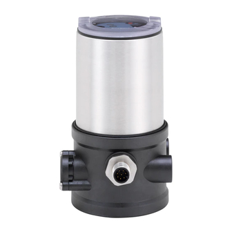
Type 8696 REV.2 System description SYSTEM DESCRIPTION Electrical connection Structure and function (circular plug-in connector) Pilot air port (label: 1) Positioner Exhaust air port (label: 3) Basic housing Actuator Transparent cap removed: Button 1 Communications LEDs Process valve interface Button 2 Valve body Pressure limiting valve Fig. 1: Structure 1 (for protection against too Positioner Type 8696 is an electropneumatic position controller for high internal pressure in pneumatically actuated control valves with single-acting actuators. -
Page 8: Model For Control Of Third-Party Devices
Type 8696 REV.2 System description Model for control of third-party “In rest position” means that the pilot valves of the posi- devices tioner Type 8696 are isolated or not actuated. A special model enables the positioner Type 8696 to be attached If the ambient air is humid, a hose can be connected between to third-party devices. pilot air outlet 2 of the positioner and the unconnected pilot This model has a different basic housing so that the pilot air air port of the third-party device for control function A or ports can be connected to the outside of the actuator. -
Page 9: Technical Data
Type 8696 REV.2 Technical data TECHNICAL DATA Ambient temperature see type label Degree of protection Conformity In accordance with the EU Declaration of conformity, the posi- Evaluated by the manufacturer: Evaluated by UL: tioner Type 8696 is compliant with the EU Directives. IP65 / IP67 according to EN UL Type 4x Rating Standards 60529 The applied standards, which verify conformity with the EU Directives, can be found on the EU-Type Examination Certificate Operating altitude: up to 2000 m above sea level and / or the EU Declaration of Conformity. Licenses 2) Only if cables, plugs and sockets have been connected correctly and in compliance with the exhaust air concept, see chapter “8 Pneumatic The product is approved for use in zone 2 and 22 in accordance installation”. -
Page 10: Type Labels
Type 8696 REV.2 Technical data Type labels Pneumatic data Control medium neutral gases, air 6.6.1 Type label (example) Quality classes in accordance with ISO 8573-1 Type, features of the type code applicable to Dust content C lass 7 max. particle size 40 µm, UL and ATEX Control function, pilot valve, max. particle density 10 mg/m³ supply voltage pilot valve 8696 -E1-...-0 PU02 Water content Class 3 m ax. pressure dew point Single act Pilot 0.6 24V -20 °C or min. 10 °C below the Max. operating pressure Pmax 7 bar lowest operating temperature Tamb -10 - +60 °C REV.2... -
Page 11: Electrical Data
Type 8696 REV.2 Technical data Electrical data 6.8.2 Electrical data, IO-Link Protection class I II as per DIN EN 61140 (VDE 0140-1) WARNING! Connection C ircular plug-in connector M12 x 1, Only circuits with limited power may be used for UL approved 5-pin, A-coded, Port Class B components according to “NEC Class 2”. Operating voltage 6.8.1 Electrical data, without fieldbus System supply communication (Pin 1+3) 24 V DC ±25 % (according to specification) Protection class III as per DIN EN 61140 (VDE 0140-1) Actuator supply Connections C ircular plug-in connector (Pin 2+5) 24 V DC ±25 % (M12 x 1, 8-pin) -
Page 12: Factory Settings
Risk of injury from unintentional activation of the system and an uncontrolled restart. Additional functions are described in the operating ▶ Secure system from unintentional activation. instructions Type 8696 REV.2. ▶ Following assembly, ensure a controlled restart. These instructions can be found on the Internet at www.burkert.com. 4) Without change to the settings via the communications software a linear characteristic is stored in FREE. english... -
Page 13: Installation Of The Positioner On Process Valves Of Series 2103 And 23Xx
Type 8696 REV.2 Installation Installation of the positioner on process → Push the positioner, without turning it, onto the actuator until no gap is visible on the form seal. valves of series 2103 and 23xx ATTENTION! ATTENTION! When mounting on process valves with a welded con- Too high torque when screwing in the fastening screw does nection, follow the installation instructions in the operating not ensure protection class IP65 / IP67. -
Page 14: Pneumatic Installation
Type 8696 REV.2 Pneumatic installation PNEUMATIC INSTALLATION Caution: (Exhaust air concept): In compliance with protection class IP67, an exhaust air DANGER! line must be installed in the dry area. Risk of injury from high pressure in the equipment/device. Important information for the problem-free functioning of ▶ Before working on equipment or device, switch off the pressure the device: and deaerate/drain lines. ▶ The installation must not cause back pressure to build up. ▶... -
Page 15: Electrical Installation
Type 8696 REV.2 Electrical installation Electrical installation without fieldbus ELECTRICAL INSTALLATION communication All electrical inputs and outputs of the device are not galvanically → Connect the positioner according to the table. isolated from the supply voltage. Safety instructions DANGER! Risk of electric shock. ▶ Before working on equipment or device, switch off the power Fig. 9: Circular plug M12 x 1, 8-pin supply and secure to prevent reactivation. Input signals of the control center (e.g. - Page 16 Type 8696 REV.2 Electrical installation Operating voltage Connection type 3-wire or 4-wire Setting via communication software Wire Configuration External circuit color Connection type 4-wire (factory setting) green 24 V DC ±25 % The set-point value input is designed as a differential input, i.e. max. residual the GND lines of the set-point value input and the supply voltage ripple 10 % are not identical. yellow + 24 V Note: If the GND signals of the set-point value input and the Tab.
-
Page 17: Electrical Installation, Io-Link
Type 8696 REV.2 Electrical installation Electrical installation, IO-Link Electrical installation, büS Fig. 10: Pin assignment, Port Class B Fig. 11: Pin assignment Designation Configuration Wire color Configuration 24 V DC System supply CAN plate/shielding CAN plate/shielding 24 V DC Actuator supply +24 V DC ±25 %, max. residual ripple 10 % L – 0 V (GND) System supply black... -
Page 18: Start-Up
Type 8696 REV.2 Start-up START-UP ATTENTION! 10.1 Safety instructions Avoid maladjustment of the controller due to an incorrect pilot pressure or applied operating medium pressure. WARNING! ▶ Run X.TUNE whenever the pilot pressure (= pneumatic aux- iliary energy) is available during subsequent operation. Risk of injury from improper operation. • Run the X.TUNE function preferably without operating medium Improper operation may result in injuries as well as damage to pressure to exclude interference caused by flow forces. -
Page 19: 10.3 Setting With Bürkert Communicator
Type 8696 REV.2 Start-up ATTENTION! Button 1 Breakage of the pneumatic connection pieces due to rota- tional impact. ▶ When unscrewing and screwing in the transparent cap, do not Button 2 hold the actuator of the process valve but the basic housing. Status LED Damage or malfunction due to penetration of dirt and humidity. - Page 20 Type 8696 REV.2 Start-up 10.3.1 Connecting IO-Link device with Bürkert Button Communicator Cutoff LED Required components: Communications interface • Communications software: Bürkert Communicator for PC Charact LED • USB-büS interface set (see accessories) Manual LED • büS adapter for communication interface (see accessories) Button • If necessary, a büS cable extension (see accessories) Status LED ATTENTION Fig. 15: Communications interface Breakage of the pneumatic connection pieces due to rota- tional impact.
-
Page 21: 10.4 Io-Link
Max. cable length 20 m 10.4.1 Information, IO-Link IO-Link is an internationally standardized IO technology (IEC 61131-9) to enable sensors and actuators to communicate. 10.4.3 Configuration of the fieldbus IO-Link is a point-to-point communication with 3-wire connection The required start-up files and the description of the process technology for sensors and actuators and unshielded standard data and acyclic parameters are available on the Internet. sensor cables. Download from: To ensure clear communication, the IO-Link devices should not www.burkert.com / Type 8696 / Software be parameterised simultaneously by the higher-level controller (PLC) via the IO-Link master and with the Bürkert Communicator (via the service 10.4.2 interface).Technical specifications, IO-Link 10.5 büS IO-Link specifications V1.1.2 10.5.1 Information, büS Supply via IO-Link (M12 x 1, 5-pin, A-coded) büS is a system bus developed by Bürkert with a communication Port Class protocol based on CANopen. -
Page 22: Control And Display Elements
Type 8696 REV.2 Control and display elements CONTROL AND DISPLAY ELEMENTS Button Cutoff LED A detailed description of the operation and functions of Communications the positioner and the communication software can be interface found in the respective operating instructions. Charact LED Manual LED ATTENTION! Button Breakage of the pneumatic connection pieces due to rota- Status LED tional impact. Fig. 17: Description of the control elements ▶... -
Page 23: Operating State
Type 8696 REV.2 Control and display elements 11.1 Operating state Button Cutoff LED To operate the buttons, make sure that the local control lock is deactivated/unlocked (factory setting): with com- Communications interface munication software or fieldbus communication. Charact LED Manual LED AUTOMATIC (AUTO) Button Normal controller mode is implemented and monitored in AUTO- Status LED MATIC operating state. -
Page 24: Display Of The Leds
Type 8696 REV.2 Control and display elements 11.3 Display of the LEDs AUTOMATIC operating state (manual LED is not lit): Button Function/LED Button Press longer than 2 s: (< 5 s, cutoff LED flashes at Cutoff LED Communications 5 Hz (0 – 2 s) and at 10 Hz (2 – 5 s)): interface Activates/deactivates CUTOFF function Charact LED CUTOFF function activated: Cutoff LED is lit yellow Manual LED Press longer than 5 s (< 10 s, status LED is lit orange): Button Starting the X.TUNE function Status LED Press longer than 2 s (cutoff LED flashes at 5 Hz (0 – 2 s) and at 10 Hz (2 – 5 s)): Fig. 19: Display of the LEDs Activates/deactivates CHARACT function Status LED (RGB) Display of the device status and valve... - Page 25 Type 8696 REV.2 Control and display elements IO-Link: Manual LED The LED mode and the colors of the valve position can be also Color Status Description set with an acyclic parameter (see parameter list). is lit Operating state HAND active The description for setting the LED mode can be found is not lit Operating state AUTOMATIC active in the section "Setting the LED mode, status indicator" in Tab. 12: Manual LED the operating instruction. Charact LED Valve mode + warnings Color...
- Page 26 Type 8696 REV.2 Control and display elements If several device statuses exist simultaneously, the device status If several device statuses exist simultaneously, the device status with the highest priority is displayed. with the highest priority is displayed. The priority is determined by the severity of the deviation from controlled operation (red LED = failure = highest priority). Valve Device status position Out of Maintenance Failure Function Status display in accordance with NE 107, edition 2006-06-12 check specifi- required...
-
Page 27: Safety End Positions
Safety end positions SAFETY END POSITIONS ACCESSORIES Designation Order no. Safety end positions after failure of the aux- Communication software Bürkert Information at Actuator Designation iliary power Communicator www.burkert.com system electrical pneumatic Connection cable M12 x 1, 8-pin 919061 Wrench for opening/closing the trans- 647078 parent cap single-acting Control down not defined function A USB-büS interface set:... -
Page 28: Communications Software
▶ During transportation protect the device against wet and dirt can be found in the associated documentation. in shock-resistant packaging. ▶ Avoid exceeding or dropping below the permitted storage temperature. Download the software at: www.burkert.com Incorrect storage may damage the device. ▶ Store the device in a dry and dust-free location. ▶ Storage temperature -20 – +65 °C. Damage to the environment caused by device components contaminated with media. - Page 30 www.burkert.com...
Need help?
Do you have a question about the Positioner TopControl Basic and is the answer not in the manual?
Questions and answers